Hi All;
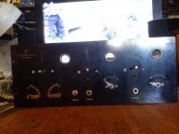
I have a STAR Radio, which I recently got, it was build in about the mid 1920's.. Does anyone have any Information on this Set..
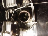
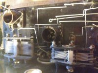
It is Missing it's Front Knobs, and all Transformers and Coils.. It is also missing any Resistors and Capacitors, except for the two Variable Capacitors.. The Variable Capacitors are two different sizes, the smaller one is about half as many plates as the bigger one.. It does have a Vari-Coupler, (think Transformer) which did not initially work, but I fixed it.. It used 01A Tubes.. But, for testing I am going to use some somewhat later tubes, but of the 1930 era..
THANK YOU Marty
From the variable cap. description, I'll guess it employs a regenerative detector and the 2nd variable cap. is the regeneration control. Does the part with more plates look something like this?
Some photos, both inside and outside may help us figure things out.
BTW, the 01A datasheet suggests that you may be dealing with a battery powered "farm" radio. Remember, rural electrification became important during FDR's "New Deal".
Some photos, both inside and outside may help us figure things out.
BTW, the 01A datasheet suggests that you may be dealing with a battery powered "farm" radio. Remember, rural electrification became important during FDR's "New Deal".
Hi All;
Eli, Thanks you Your Answer, my Guess was at first it Could be a Regenerative or a Super-Regenerative.. But, there is the possibility that it might be a TRF Set and that the Second Capacitor might be a kind of fine tuning.. It is not what was technically a Farm Radio, I have a Superhet that is truly a Farm Radio.. I'LL see about some pictures of the Unit, next, then I need to figure out How to upload them..
THANK YOU Marty
Hi All;
Eli, Thank You for the 01A Datasheet, my RCA Manual, basically only states that it is an outdated tube and is for Reference..
So, Yes, I needed a sheet with Information like it contains, maybe that will give me more of the Information that I need to make it Work, Photo's will be next..
THANK YOU Marty
Hi All;
I am still trying to figure out "how" to do Attachment photo and multiple photo transfers..
THANK YOU Marty
I am still trying to figure out "how" to do Attachment photo and multiple photo transfers..
THANK YOU Marty
Hi All;
I am going to try and upload some Attachments..
View attachment 711268 View attachment 711269 View attachment 711270

THANK YOU Marty
I am going to try and upload some Attachments..
View attachment 711268 View attachment 711269 View attachment 711270

THANK YOU Marty
Last edited:
That's a lovely old radio. The '01 had a 2.5 V filament and was used in all sets, home and otherwise. The three holes allow the user to see the filaments as they adjusted the filament current. It was judged by the brightness of the filament. It was very probably a TRF radio.
I would love one of those for my collection, so look after that one.
One common failure was open transformers. THe primary wire used was so thin that they often corroded and broke. Keeping these radios dry is very important.
-Chris
I would love one of those for my collection, so look after that one.
One common failure was open transformers. THe primary wire used was so thin that they often corroded and broke. Keeping these radios dry is very important.
-Chris
Hi All;
Anatech, I suspect that this radio has gone thru many hands, and as far as I can tell no one had made any progress on the set..
Here are some pictures from Radio Museum (three of them)
Star Radio Mfg. Co.; Oakland, CA, 3-Tube Receiver, 3 picture
The open primaries, could have been why the Transformers are missing, or they were sold for their copper..
THANK YOU Marty
Marty,
Without proper documentation, all of us are making, at best, "educated guesses". Would you be up to cobbling a PSU together, possibly in a 2nd "box"? The 5 VDC for 01A filaments is easy enough, courtesy of a 7805 IC.
AnTek's AS-05T120 power trafo seems electrically suitable. FWCT the 2X filament windings with a DSTF10200C twin Schottky diode, cap. filter, and 7805 regulate. Bridge rectifying the "100" VAC tap rates to work well for B+.
Hi All;
Eli, I realize that "" Without proper documentation, all of us are making, at best, "educated guesses". ""
At Present the Power Supply Issue is not the problem, I have made the Vari-Coupler work, it had an open, I have mostly made the larger Variable Capacitor work with a coil that I have wound, I am in the process of winding a coil and finding something that will work with the smaller coil, both as Tank Circuits for tuning..
My next step is to make it into a glorified two stage crystal set, and see about getting signals to go through it..
So far I have only done this with the one larger Variable Capacitor, using three frequencies, 540KHZ, 1000KHZ and 1700Khz.. And the Vari-Coupler..
Also, as a side not I will soon be getting a CD of all six volumes of the pamphlet's "The Impoverished Radio Experimenter"..
I have volume 5 in paper, and some day when sufficient funds are available, I will (hopefully) get the rest in paper as well.. But, all 6 volumes in CD cost the same as one Paper Volume..
This seems to hopefully will help me make the pieces work that I don't have completely worked out..
THANK YOU Marty
Last edited:
Ryders are the best place to find that info and it's free.Hi All;
I have a STAR Radio, which I recently got, it was build in about the mid 1920's.. Does anyone have any Information on this Set..
It is Missing it's Front Knobs, and all Transformers and Coils.. It is also missing any Resistors and Capacitors, except for the two Variable Capacitors.. The Variable Capacitors are two different sizes, the smaller one is about half as many plates as the bigger one.. It does have a Vari-Coupler, (think Transformer) which did not initially work, but I fixed it.. It used 01A Tubes.. But, for testing I am going to use some somewhat later tubes, but of the 1930 era..
THANK YOU Marty
Hi All;
Michaelsamra, "" Ryders are the best place to find that info and it's free. ""
Only Ryders, doesn't show it !! I had already checked.. But, I have not checked Sam's, but, I suspect it will not have anything, since Sam's starts in the 1950's..
THANK YOU Marty
Michaelsamra, "" Ryders are the best place to find that info and it's free. ""
Only Ryders, doesn't show it !! I had already checked.. But, I have not checked Sam's, but, I suspect it will not have anything, since Sam's starts in the 1950's..
THANK YOU Marty
Hi All;
Today, I am going to wind the coil for the smaller Capacitor, since it is about half as many plates as the other one..
I am going to wind about Double the amount of turns as I did for the Large Capacitor, and make taps at 5 turns before the end of what I think is needed, tap ever 2 turns till I am 5 turns over..
I can then try it at the three frequencies, like I did the other one, and finding the best tap for the smaller Capacitor, the I can wire the two tuned sections in parallel, which hopefully it will then allow the signal to be tuned by the first section, and finely tuned by the second section..
Well, that is the plan for today, for now.. I will let Everyone know what the outcome is in awhile..
THANK YOU Marty
Hi All;
Success, I have make it so that all three frequencies, will go thru the Vari-Coupler and then the Larger Variable Capacitor then thru the two coils, Secondary on the first tuned coil and Primary on the second tuned coil, then to the small Variable Capacitor, where it is tuned by it, and viewed by the Scope..
When I tuned using either the small or the large Variable Capacitor it would tune to the lower frequency the most (640KHZ) and the higher frequency the Least (1700KHZ..
Now with both tuned circuits, they all tune to about the same level of Output..
At this point, there are no Tubes attached to the Radio, and input is from a Precision Signal Generator Model E-200-C..
So, what this means is that I can make this Radio into a TRF type of set..
THANK YOU Marty
Last edited:
Marty,
You will have a very tough time using the 01A as a RF amplifier. Unless very carefully neutralized, you will end up with an oscillator.
A grid leak detector followed by common cathode AF amp stages rates to be successful. For the AM broadcast band, a 250 pF. mica cap. and 2.2 Megohm carbon composition resistor work well, as the grid leak combo.
You can mess around with regeneration, after the straight forward grid leak setup is functioning.
You will have a very tough time using the 01A as a RF amplifier. Unless very carefully neutralized, you will end up with an oscillator.

A grid leak detector followed by common cathode AF amp stages rates to be successful. For the AM broadcast band, a 250 pF. mica cap. and 2.2 Megohm carbon composition resistor work well, as the grid leak combo.
You can mess around with regeneration, after the straight forward grid leak setup is functioning.
Hi All;
Eli, Thank You for Your Insight and Answer..
For now I will NOT be using any 01A's, as I don't have the Money for any of them..
It will be mostly proving out the Circuits, with what I have and can get working..
At this stage, I want to get this whole thing to function somewhat correctly, before Investing in any 01A's..
And, so for now, it will be getting one stage working, before figuring out what will be next..
Basically, what I wanted to do, I set out to do first, I did it, by getting a signal to pass through, and thereby proving that (one) I could get the capacitors to tune and (second) that like there was no Shorts in the components that I have or am using..
Basically, for starters, it is not a piece of Junk..
Eli, Using the old 4 pin thru 7 pin type of tubes, what tube or tubes, would You suggest for a tune-able RF Amp ?? Like for a TRF setup..
THANK YOU Marty
Last edited:
- Status
- Not open for further replies.
- Home
- Amplifiers
- Tubes / Valves
- STAR -- Unknown Radio

