Hi All;
Demonkleaner, Thank You for the Encouragement..
I can't Tell from the Pictures, What Brand of Radio do You now have ?? (and)
What Tubes does it use ?? Are they 01A's ??
It looks nice on the Inside and the Outside..
THANK YOU Marty
Demonkleaner, Thank You for the Encouragement..
I can't Tell from the Pictures, What Brand of Radio do You now have ?? (and)
What Tubes does it use ?? Are they 01A's ??
It looks nice on the Inside and the Outside..
THANK YOU Marty
Eli, Using the old 4 pin thru 7 pin type of tubes, what tube or tubes, would You suggest for a tune-able RF Amp ?? Like for a TRF setup.
Definitely a pentode, to avoid the neutralization problem. RES shows reasonable prices for the 39/44 and 38 you mentioned. However, just because there's a listing doesn't mean stock on hand. Call them to find out.
Hi All;
Eli, one of the Reasons that I choose these tubes, is that I have exactly what I need for these tubes..
I have two of the 39/44's and one 38..
I could have one or two more that I haven't found, but this will get me started..
THANK YOU Marty
Eli, one of the Reasons that I choose these tubes, is that I have exactly what I need for these tubes..
I have two of the 39/44's and one 38..
I could have one or two more that I haven't found, but this will get me started..
THANK YOU Marty
Hi Demonkleaner,
Beautiful set! I could only wish to find something in as good a shape up here. The old radios are mostly in rough cosmetic shape. Probably due to our climate.
-Chris
Beautiful set! I could only wish to find something in as good a shape up here. The old radios are mostly in rough cosmetic shape. Probably due to our climate.
-Chris
Hi All;
I have made a coupling coil, between the vari-coupler and variable Capacitor..
One side of the coil is the same resistance as the vari-coupler and the other coil is what is needed to tune to the AM Band, per my three Frequencies..
So, next is to copy the Schematic from the RCA tube Manual RC-10, and adapt it to what I have for the first two tubes.. (39/44)..
Get that wired up and working, easier said (Typed) than done..
THANK YOU Marty
...You will have a very tough time using the 01A as a RF amplifier....
Agree--- however everybody but RCA made lots of '01 TRFs. (RCA had a better patent but their tubes were crap.)
The RC-10 '39 plan (below) is, of course, screen-grid tubes. Do you have the sockets for '39? My understanding is that the coils will be "very" different. With triodes you do NOT want big gain, it will be unstable. With screen grids you go for the gain.
And the RC-10 plan calls for an astonishing >300H plate choke. OK, with a pentode driving 1Meg, 300H is good down to like 250Hz, so that's not wrong.
I have zero doubt that you could hide a few JFETs in there and make a working TRF radio. (JFETs are screen-grid tubes without a screen grid.)
Interesting: Radiola 16
Attachments
Last edited:
Hi Demonkleaner,
Beautiful set! I could only wish to find something in as good a shape up here. The old radios are mostly in rough cosmetic shape. Probably due to our climate.
-Chris
Thanks Chris
An older collector was "thinning the herd" at a local swap meet. He has the matching speaker but didn't have it with him. Hope to persuade him to sell it to me. The battery leads are pretty much gone so that will need to be addressed. The required PS is a bit complicated but I'm working on it. It used 5 separate batteries!
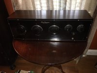
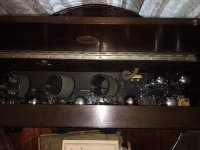
Marty: Yes they're 01A's. It has two of them in parallel for the audio out. Haven't tested them yet though. Radio is a Freed Eismann model NR-7. Not nearly as rare as your Star. I did some looking and other than the radio museum photo PRR posted, I can't find anything. I have all of the Ryder manuals on DVD and nothing there either. I wrongly stated that I the Sams photofact manuals the other day. I may also have a set of knobs from a donor radio (if they're the right diameter) that may fit your set.
Hi All;
PRR, Thank You for the information..
"" The RC-10 '39 plan (below) is, of course, screen-grid tubes. Do you have the sockets for '39? ""
Yes, I have the tubes and the sockets..
"" I have zero doubt that you could hide a few JFETs in there and make a working TRF radio. (JFETs are screen-grid tubes without a screen grid.) ""
I do NOT plan on using Jfet's, this is a Tube Radio..
The attached Schematic is the one that I am going to adapt to try and get it working..
DemonKleaner, "" I may also have a set of knobs from a donor radio (if they're the right diameter) that may fit your set. ""
I would definitely be interested in the knobs, I will check the Diameter, but, I think there 1/4 inch..
THANK YOU Marty
Last edited:
you will have to wind your coils exactly as shown, as tuning happens between the 3.
coil diamater and wire spacing do count.
coil diamater and wire spacing do count.
Hi All;
Stocktrader, "" you will have to wind your coils exactly as shown, ""
Shown where??
"" as tuning happens between the 3. ""
What three ??
"" coil diamater and wire spacing do count. ""
I have worked out between my Variable Capacitor and my coil form, so tuning seems to work..
THANK YOU Marty
Stocktrader, "" you will have to wind your coils exactly as shown, ""
Shown where??
"" as tuning happens between the 3. ""
What three ??
"" coil diamater and wire spacing do count. ""
I have worked out between my Variable Capacitor and my coil form, so tuning seems to work..
THANK YOU Marty
Hi All;
A couple of things, one is I am pretty sure that this radio is a Prototype or first attempt at making a set..
But, my thinking is that after they made it, they found out about Armstrong's Super-hetrodyne, and so did not develop this set any further..
And that one of the Engineers or Investment people hung on to the set all these years, till they were dead.. And it was then sold on an Estate sale..
I have almost finished my Coil for this radio, all of the winding is done, and all I have to do is Attach the clips to hook it into the rest of the Set..
I have one good Transformer, and will eventually need a second one to finish it, but, that can wait till I get the first part all wired up, or fix one of the others I have..
THANK YOU Marty
That's a real company though I doubt they made many/any for sale.
TRFs were made/sold for some time after the SuperHet came forward. SuperHets can be ultimately simpler/better but need special parts (gang caps with different sections, IF transformers). Also you would (should) pay to use Armstrong's patent. Which was disputed for a long time, but most in the field assumed "someone" would take the money, only a question of "who" (Westinghouse, Lévy, GE, Bell Labs...) For local reception of one/few stations, the TRF was practical and nearly risk-free.
OTOH, it was also made by everybody and his dog. So the STAR folks may have done the prototype, figured a selling price of say $49, then found $39 and $29 TRFs all up and down radio-row.
Hi All;
PRR, Thank You for Your Answer and Your Input..
Yes, You could be right.. But, now that I have looked at it, I am thinking it is a Three Tube Regenerative Set, and Not a TRF, since the Variable Capacitors are of different sizes and so that might fit the Regenerative circuit better..
I hope to soon to be Looking more care fully thru the Various Radio -- Wireless Magazines that I have Downloaded in PDF format, and see if that might be of any help..
I am concentrating on the late 1920's in my magazine search, and I will see what I can dig up..
I have Popular-Radio, from 1922 thru 1928, Radio 1922 thru 1931, and Radio-World from 1922 thru 1939..
I am hoping that looking thru these will help my radio education, and narrow down the possibilities of what I want to build this STAR into..
I have already found the Variable Capacitors that are used in this set in some Advertising..
THANK YOU Marty
FWIW, I'm inclined to agree with the regenerative assessment. A regenerative detector followed by 2X step up transformer coupled AF stages meshes very well with the low amplification factor (μ) of the OEM 01A. The tubes impedance match at least as much as they provide voltage gain.
BTW, has thought been given to converting the electrical signal into audio? The high impedance magnetic headphones used way back when are not easy to source nowadays. It may make sense to use something like this, in combination with a transformer. You gain a DC block between what's on your head and the B+ rail.
BTW, has thought been given to converting the electrical signal into audio? The high impedance magnetic headphones used way back when are not easy to source nowadays. It may make sense to use something like this, in combination with a transformer. You gain a DC block between what's on your head and the B+ rail.
Hi Marty,
Do you have a photo and specs of the capacitor(s) you need? Also have you made a decision on which tubes to use? I may have something usable. Judging from the 1:3 transformer I assume the 1:6 is 1K:6K. With the low voltage and currents involved, you may be able to source a small transistor output transformer and put it into the old transformer housing to keep the authentic appearance. The knobs I have are for a 1/4" shaft but you'd need to check the outer diameter to be sure they don't cover up your scales and markings of your faceplate. Keep us posted!
Do you have a photo and specs of the capacitor(s) you need? Also have you made a decision on which tubes to use? I may have something usable. Judging from the 1:3 transformer I assume the 1:6 is 1K:6K. With the low voltage and currents involved, you may be able to source a small transistor output transformer and put it into the old transformer housing to keep the authentic appearance. The knobs I have are for a 1/4" shaft but you'd need to check the outer diameter to be sure they don't cover up your scales and markings of your faceplate. Keep us posted!
Hi All;
Demonkleaner, at present I don't need any capacitor(s) as the two that I have will (Hopefully) work for tuning, etc..
I may need something for grid leak, but that has to be worked out.. I at this point need to find a three tube Regenerative circuit that will fit what I have..
Then I will know if I need any more Caps, etc..
As far a knobs are concerned, the small ones are a tapered knob that measure about an 1" and a 1/4 across..
"" Judging from the 1:3 transformer I assume the 1:6 is 1K:6K. "" That is my thought..
I am going to put the 1:6 transformer back together, before I forget enough of how to put it back together..
"" Also have you made a decision on which tubes to use? I may have something usable. ""
I was going to use for now 39/44's, but, now that I have decided to go Regenerative, I have to see if these will work and a 38 for the Output..
Eli, I have a set of cheap Headphones that are from that period, that should work..
THANK YOU Marty
Hi All;
I have found a circuit that I can use as a place to start, and adapt it to what I have..
Here is the Link::
Taylor Electric 3 tube Regenerative Radio - The RadioBoard Forums
It's a Taylor Electric 3 tube Regen..
THANK YOU Marty
I have found a circuit that I can use as a place to start, and adapt it to what I have..
Here is the Link::
Taylor Electric 3 tube Regenerative Radio - The RadioBoard Forums
It's a Taylor Electric 3 tube Regen..
THANK YOU Marty
Possible resource Star City Antique Radios and Test Equipment
Also I do have the rider manuals. If you find a set compatible with yours, I may be have some information. I'm very new when it comes to these radios. I have several because my wife thinks they're "pretty"..........
Also I do have the rider manuals. If you find a set compatible with yours, I may be have some information. I'm very new when it comes to these radios. I have several because my wife thinks they're "pretty"..........
- Status
- Not open for further replies.
- Home
- Amplifiers
- Tubes / Valves
- STAR -- Unknown Radio