.... ...... Also, when I did HD compensation in the dac registers for H2 and H3, I could only reduce them maybe a couple of dB each. One, H2, required a tweak of 5 out +-32,000 and H3 was lowest with a setting of -6.
so I suppose you still measured some HD then? if yes, then may I ask what was the noise floor upon the measurement and the starting H2 and H3 values?
I don't know what the noise was, don't remember if I was signal averaging or not. Also, I don't have a good absolute calibration here, but as close as I can recall eyeballing it, one of them was -122dB or -124dB, but this was with 100MHz clock and 11.2MHz DSD. So, I guess must have been averaging out noise.
To be very clear on this, it was not my intention when doing this to get calibrated harmonics of a 1kHz tone, and or noise too, only to minimize H2 and H3 given there are registers to do it.
Don't know if you are aware of it, but when Allo shipped out Katana 1.0 it tested fine at the factory for 1kHz THD however they measure it. It didn't sound right to me and I told them so. On getting my report they ran more extensive tests and found there was a problem with HD that only showed up if the test tone was 10kHz or higher. They recalled all the dacs they sent out to reviewers to fix it. They said something got misconfigured in the firmware. They were surprised I could hear it, but they ran the tests because they trust that I know what I am doing.
So, I primarily listen and compare to DAC-3. I am not equipped to do proper testing of dacs. If you go to Stereophile and look at the measurements they did of DAC-3 you will see there are a set of measurements needed and listening too.
Look, I would be happy to cooperate with someone around where I am if someone who is equipped to do so wants to run extensive tests on the dac I have modded and the one I am still working on. But, I have always said in this thread it is a diy project that people can do without test instruments, we will do the best we can with the resources we have as amateurs with small budgets for this hobby. I think we are doing quite well in that context, although there may be some things we do that are a bit of overkill. Since we are making one off modded dacs I think that is okay. A little overkill is cheaper than a lot of expensive test equipment.
And, so far my 1st modded dac has sounded as good or better than Allo Katana up to v1.1. We will see again when Katana 1.2 is out. One of the reviews of RPi dacs and who sells competing brands already found that Katana 1.1 is the best RPi dac on the market. No surprise there. Allo put a lot of engineering effort into it, and they say they only made one mistake: They relied too much on measurements and not enough on listening tests.
Last edited:
Interesting link about Allo Katana v1.2 over here: https://www.diyaudio.com/forums/vendor-s-bazaar/294940-fifo-buffer-rpi-sbcs-248.html#post5567242
In that post there is also link to some description of the Ayre QC-8 dac which uses the same dac chip we use here, ES9038Q2M: My Quest for a new DAC, Part 2 - Ayre QX-8 - Reviews - Computer Audiophile
In the QX-8 they do the stuff I have said would need to be done with our modded dacs to make them any better than they are. Lower frequency, lower jitter clocking would needed. Also, we would need to do external interpolation filtering in an FPGA, maybe a Spartan 6 (which is why I keep saying ES9038PRO may have an advantage over Q2M since is can be operated with more filter taps if limited to stereo operation). We aren't doing those things, but we are doing many of the things that are needed to make a very good dac with the dac chip we have. No surprise it performs very well and sounds good.
We did talk here briefly about a possibility of using Surfboards (or equivalent) and SMD resistors and caps instead of some of the leaded resistors and caps. If there are people who think that kind of SMD construction might be doable and of interest, I would encourage anyone to give it a try.
If enough people think they might want to go that way if given an option, maybe the BOM could be expanded to include parts for an SMD-on-adapter version.
If there is any interest for something like that, please raise your hand (figuratively) so we can see how many. Otherwise, we will stick with what we have already for the parts list, and only make a few corrections/updates.
So far no hands raised, nor any other affirmative response.
I will give it another day or so in case of any late responders. If none, then we can proceed as is.
Hi Andy,
Thank you for the reply. Let's give it a little more time to see if anyone else feels the same way.
Thank you for the reply. Let's give it a little more time to see if anyone else feels the same way.
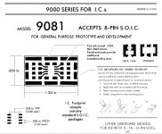
While waiting for a part to arrive to get me going again, did a little thinking about an SMD version of the through-hole output stage schematic. It would be based on three model 9081 Surfboards with the outline as in the pic attached below.
The three Surfboards would be enough hold all the components. If laid out flat they should be able to fit in about the same space as the leaded component version, so they could probably mounted on the same size PCB.
I ordered a few surboards to take a closer look at how that might work. Need to order a few SMD resistors and capacitors too. Be something interesting to try out.
Attachments
After looking into SMD parts a little more it turns out the resistor values we need are not available in tighter than .1% tolerance, at least for in-stock items. So, ordered the resistors and caps that are reasonably available for an SMD output stage using the new filtering.
Actually, I think it might turn out to be easier to assemble than the through hole (leaded) component version. We'll see, I guess, when all the parts are here. A possible downside for some modders is that there are no sockets for trying different opamps, not that swapping opamps should be needed. LME49720 is an excellent choice for this application.
Actually, I think it might turn out to be easier to assemble than the through hole (leaded) component version. We'll see, I guess, when all the parts are here. A possible downside for some modders is that there are no sockets for trying different opamps, not that swapping opamps should be needed. LME49720 is an excellent choice for this application.
Mark at which position is needed such small tolerance SMD resistor? I see on output stage but which resistor ?
It probably helps to have all the resistors be tight tolerance because it helps to make the output stage more effective at removing common mode noise. Differential combining requires resistors in accurate ratios, and matched I/V resistors keep common mode currents from appearing as differential mode signals.
The 220 ohm output resistors could probably be looser tolerance so long as the input impedance of the power amp or preamp that follows is high enough. However, a couple of good resistors are cheap enough to just use the same kind as for other parts of the output stage and not worry about it.
The 220 ohm output resistors could probably be looser tolerance so long as the input impedance of the power amp or preamp that follows is high enough. However, a couple of good resistors are cheap enough to just use the same kind as for other parts of the output stage and not worry about it.
Last edited:
Hey Markw4,
why not try the suggestion of abraxalito that showed good results in simulation instead of copying the one you already built?
ES9038Q2M Board
so you could compare between several stages. Further in case of SMD I think your orig. idea of modifying the already existing on board output stage and using it as symmetric stage saves space and makes the setup more compact with shorter wires..
Hey Freezebox,
It looks like both the one I am doing and the one Abraxalito is doing are multi-feedback, and are pretty similar. Not sure there would be significant reason to try another. However, I would happily invite you to build multiple versions to compare.
My feeling at this point is that we can probably gain something by more filtering than my 1st dac had, but perfection of sound quality will not come from trying to perfect the things we are already doing pretty well, it would come much more from starting to do the things that we are completely ignoring, such as external interpolation filtering. I actually have a low end Chinese Spartan 6 board to play around with when I have time. However, I don't expect to do that until this through hole business is finished. It is more important for me to see some people modding dacs rather than me going off to work on new things. All things in due time, as they say. Maybe so, we'll see.
Regarding reusing the original output stage space on the dac board, I'm afraid it will mostly be used up by the huge film caps I will be testing for AVCC output filtering. However, I look forward to seeing your builds as a showcase for your ideas. Please be my guest and write about your work here. We would all enjoy reading more interesting content.
Once again, the reason I am here is to help make low cost high quality dacs available to more people. If I can't get a few people to fully mod some dacs and talk about how they sound to other people, and show that it can be done and is worth doing, then my time is wasted.
Similarly, there is no point in me adding complexity to modding dacs with more chips if I can't get anyone to build at the complexity we already have.
One sort of new thing I just started doing is posting a bit in other threads, and trying to see if iancanada would be interested in some of the mods we do here. If so, he builds boards of things he likes and sometimes offers them for sale, at least for awhile. In that case it might be a way for people to buy a finished dac board with some of the ideas and sound quality benefits from here.
The thing is, as good as one of these fully modded dacs can sound, nobody has one but me. Nobody cares to build one so far, but me. Nobody outside of this thread cares that such know-how exists. Typical for new ideas, or assemblages of ideas. It isn't enough to make something good. Then you still have to sell the idea to others, who are generally jaded and uninterested. That's the way it is. Well, word of mouth is best if you can get it. If a few people would just build, then maybe we could start to have some word of mouth.
Hey, just wondering, how is your project coming along? We would love to hear of any progress. 🙂
@Freezebox,
Thought maybe I should comment a little more a long wires and short wires, since you raised the issue. Actually, its probably a good thing that you did.
We probably all know by now that we are trying to keep the AVCC wires very short and very low impedance going into the dac chip. That does seem to help with sound quality, and it is something ESS has recommended.
What about the differential output signals from the dac chip to the I/V stages? In that case with the through hole component output stage board bit farther away than the original output stage, might we expect that to be a problem? Actually, maybe it is an opportunity. If we twist the differential output pairs together and keep them close to the ground plane on their way to the output stages that might be a good thing. Some capacitance between them and some capacitance to ground might help to filter out some RF that otherwise might filtered with a lumped capacitor. Twisting the wires together also helps to prevent magnetically coupled noise pickup, and being close the ground plane helps with electric field pickup. In addition, they are fairly low impedance which can help too.
Regarding the distance of the output signals from the differential summing stage to the RCA connectors, in most cases people will probably still be using the existing RCA connectors on the side of the dac board, whatever that distance is. If desired, little coax cables (shield grounded on one end only) could be run from 220 ohm output resistors to the RCA connectors, or one could just run the wires away from the input wires and circuitry as much as possible, maybe around the one side of the output stage board and patch into the traces on the dac board that go to the RCA connectors.
Of course, noise performance should be expected to be the best if the dac is put in a good quality well shielded case. 18 gauge steel can be good for shielding, and it can be lined with copper foil as well, although that should not be necessary except in unusual cases. Best to keep the dac board well centered if in a steel case as we don't want the signal wires too close to the steel, since it can increase inductance if there is coupling. Maybe 2" away should be enough if you have the space to spare. If not, then I would say do the best you can. DAC-3 is in a steel case which is a good idea if using LME49860 or LME49720, but the PCB comes close to the steel without apparent concern. However, I doubt the are long traces with sensitive signals running parallel to the case walls along the edges of the PCB. A little common sense can go a long way towards avoiding any problems. Mostly I am just speaking out of an abundance of caution here. Not expecting there will be any problems.
Last edited:
Hello Markw4,
I like your sense for details and detail solutions! You asked for my current project status - it is still like this and that.
I am so happy listening all the details and dynamics that I feel no big need for further improvements... nevertheless I am thinking about placing an order at mouser for a crystek clock and some LDO for powering the MCU and DVCC DAC inputs separately such as a LTC6655 for AVCC opa ref.. And probably order the more expensive Ak4137 SRC board (btw. - does it have I2S inputs beside the coax?).
But I am also curious on your results with film caps for AVCC, so wanted to wait until I hear your report about it. But as you mentioned the long wires before, isn´t a big cap also a catcher for RF noise? And does the distance between the pins add some impedance compared to small caps? Guess you will place the AVCC cap with the shortest pin directly to the orig cap "+" solder point and the long end to the GND?
Hi Freezebox,
Of course, you are quite welcome for any information that can help you with what you want to do.
I sure hope you will keep modding. If you do, you will still have details and dynamics. But it will sound better than it does now, more natural and less distorted, less clinical if you want to call it that.
What I am doing for power for all the low voltage devices (<15v) on the dac board is I have disconnected the 5v (or 8v) 3-terminal regulator on the dac board and use an external 5v supply for all boards including the dac board that need low voltage power. The external supply is a Chinese LT3042 board with an output transistor attached and rated for 1A. I increased Cset to maybe 20uf for lower LF noise, but that also required me to do a fast start mod on it in order for the AK4137 board to boot (it needs power to come up faster). I think the regulation of the 5v is overkill for what I need, it could be a much more modest performance regulator, it was just something I had.
On the dac board there is an existing 1117 type linear 3.3v regulator. I let that run the MCU and DVCC. For the clock, I use a dedicated LT1763-3.3 with mostly SMD caps (including a cap to lower the regulator noise) and I solder the LT1763 directly to the dac board ground plane, or at least the pins that need grounding. I also use a dedicated LT1763 mounted the same way for VCCA. That arrangement seems to work fine. Nothing more exotic is required, so far as I can tell.
For +-15 volt power I use a dual stage regulator that is LM317/337 followed by LT1963 type regs for the 2nd stage. That's probably better in a lot a ways than one LDO trying to do it all. People are finding those things look good on paper but don't sound equally good for dacs. I haven't really looked into why except to see that they have low frequency noise that could matter for some dac circuitry, and they can probably ring on sharp current transients in some cases if trying to drive a lot of distributed circuitry.
To answer your question about the more expensive AK4137, yes, it does I2S/PCM/DSD as well as SPDIF, TOSLINK, and AES/EBU.
Regarding big AVCC caps, I don't think there should be a lot of RF where I am putting them. The will go on top of the board with one pin going through the existing AVCC cap hole, and the other pin will go through a hole in the board to the ground plane on the bottom. They will extend down towards the output stage board. The ground plane return for the AVCC cap should have low inductance. If the thing filters well up to 100kHz or so I think it will probably be doing fine. That would be similar to an electrolytic. We don't necessarily want a cap in there that is good to many MHz or it might be more likely to make the opamp regulators unstable. We'll see how it works is all I can say.
I also want to try AD797 AVCC regulators instead of LME49720. I will say a bit more about that a little later. According to what ESS says, they were able to get a little bit lower harmonic distortion that way. Again, we will see how it works and if any audible improvement.
The other thing I am thinking about for AVCC has to do with mounting the through hole component AVCC board on the dac board. I may turn it around the pointing the other way, and also angle it a bit so it misses pins sticking out on the bottom of the ground plane. That's mostly in case I ever want to unsolder whatever topside components those pins are for on the bottom of the board. If I block access to the pins with the AVCC board, that might come back to bite me later.
Wanted to say a little bit about preparing to try AD797 for AVCC and about micro-soldering.
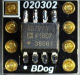
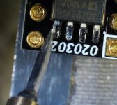
First, decided to try some new-to-me SOIC to DIP single to dual opamp adapters. The sockets on my AVCC and output stage boards are wired for dual opamps. AD797 is a single. Turns out there are some very compact adapters that look very interesting for this type of thing: Single to Dual Op Amp Adapter | BrownDog 020302 | Cimarron Technology
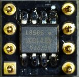
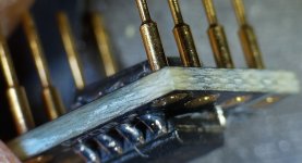
Some pictures below of one of the adapters with two AD797 soldered to it. Pics also show the tip of a Hakko micro soldering iron. The tip is a knife edge which makes it thin enough to fit between pins and only touch and heat the desired pin. Because the tip has a rectangular cross section, it has enough area for good heat transfer. What it can do is truly amazing. I soldered AD797's in place one pin at a time, no problem.
I also tried the tip on some scrap boards for pin lifting use. It is possible fit the knife edge between pins, melt the solder for on pin, the wedge the knife under the pin and lift while the solder is still molten. Make it incredibly easy for the pins I tried it on.
First, decided to try some new-to-me SOIC to DIP single to dual opamp adapters. The sockets on my AVCC and output stage boards are wired for dual opamps. AD797 is a single. Turns out there are some very compact adapters that look very interesting for this type of thing: Single to Dual Op Amp Adapter | BrownDog 020302 | Cimarron Technology
Some pictures below of one of the adapters with two AD797 soldered to it. Pics also show the tip of a Hakko micro soldering iron. The tip is a knife edge which makes it thin enough to fit between pins and only touch and heat the desired pin. Because the tip has a rectangular cross section, it has enough area for good heat transfer. What it can do is truly amazing. I soldered AD797's in place one pin at a time, no problem.
I also tried the tip on some scrap boards for pin lifting use. It is possible fit the knife edge between pins, melt the solder for on pin, the wedge the knife under the pin and lift while the solder is still molten. Make it incredibly easy for the pins I tried it on.
Attachments

Tomorrow I hope to be back in the game here, making progress on the through hole component dac. Parts are supposed to arrive around midday. Ready to get back to work, never like waiting for parts.
Nice adapters, don*t use dil socket, use right solder because each solder has different sound even with the same opamp. This joints don*t look perfect...if we are talking about perfection. More solder is not always good. Best conntact has opamp copper pin dirrectly press to golden plated conntact of adapter. No solder between them or as least as possible. Little solder most just be around pin and surface to keep this conntact tight.
My receipe... put opamp on right pin position, then solder pin 1 or 8 that are not important. Then use Mini-Alligator Clip with Smooth Jaws to press opamp to surface and do fine quick joints. I use wbt solder. At the end i put pins into adapter and solder it. Clean everything with isopropil and toothbrush.
My receipe... put opamp on right pin position, then solder pin 1 or 8 that are not important. Then use Mini-Alligator Clip with Smooth Jaws to press opamp to surface and do fine quick joints. I use wbt solder. At the end i put pins into adapter and solder it. Clean everything with isopropil and toothbrush.
Tomorrow I hope to be back in the game here, making progress on the through hole component dac. Parts are supposed to arrive around midday. Ready to get back to work, never like waiting for parts.
Hi Mark,
Happy to see that these mods are going well in term of SQ and I will be very interested by the arduino mod.
I received some of the composants and waiting for the remaining and the AK4137.
Once you will be satisfied by the differents mods, will you post a precise BOM for each of them?
Maybe it could help beginners like me.
The BOM bih made is good except for one part for the AVCC board. That part is the 47uf AVCC filter cap that goes in the dac board. He has it has being tantalum, but it should actually be aluminum electrolytic or aluminum organic polymer.
Is this one ok?
A750EK476M1EAAE040 KEMET | Mouser France
Thank you
@terry22,
Yes, I think that cap should work okay. I am planning to experiment with a different cap, in case you want to wait and see how that turns out, but probably not necessary. I am not expecting much if any difference. More along the lines of just checking to make sure.
Also, an updated BOM will be finished at some point although the one we have now is mostly good. The only issues I am aware of are the 47uf cap that you are asking about, and that an AD797 should not currently be included.
- Home
- Source & Line
- Digital Line Level
- ES9038Q2M Board