I'm looking at adding an external I2S board to the DAC.
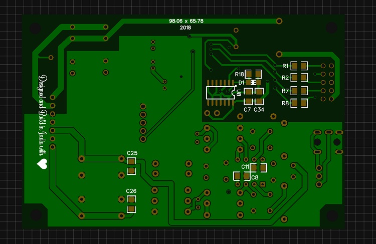
The idea is to make a small pcb, connected between R12, R13, R14 and R15 pads.
The small piggy back pcb would hold the above resistors, one socket for plugging the external board and two relays for switching between the external and internal I2S options.
The idea is to make a small pcb, connected between R12, R13, R14 and R15 pads.
The small piggy back pcb would hold the above resistors, one socket for plugging the external board and two relays for switching between the external and internal I2S options.
Attachments
AK4396 24/196 DAC in Parallel Mode
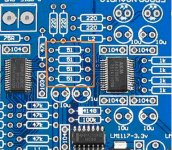
Hey guys, from couple of days i am working on a pcb for AK4396vf DAC Chip. it accepts external i2s, no on-board reviver for output stage stock single opamp with external header to bypass onboard opamp and for source CMedia CM6631A for DIYINHK usb receiver.
After building i am planning for discreet staging..!
Any Suggestions..! 🙂🙂🙂🙂
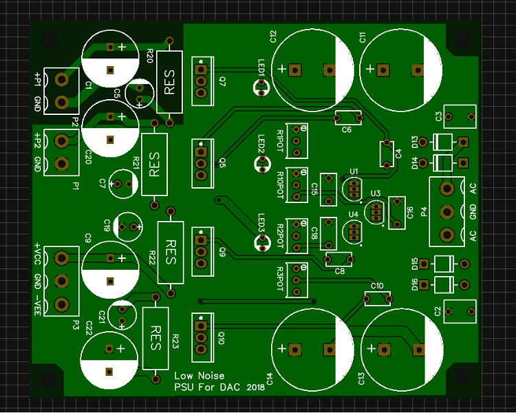
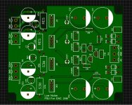
Low Noise linear PSU for DAC with LM329DZ Voltage Reference and LM4562MAX op-amp driving IRF640 Mosfet
Hey guys, from couple of days i am working on a pcb for AK4396vf DAC Chip. it accepts external i2s, no on-board reviver for output stage stock single opamp with external header to bypass onboard opamp and for source CMedia CM6631A for DIYINHK usb receiver.
After building i am planning for discreet staging..!
Any Suggestions..! 🙂🙂🙂🙂
Low Noise linear PSU for DAC with LM329DZ Voltage Reference and LM4562MAX op-amp driving IRF640 Mosfet
Attachments
Last edited:
AK4396 24/196 DAC in Parallel Mode
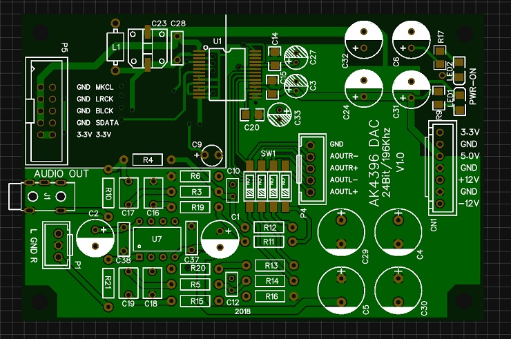
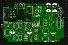
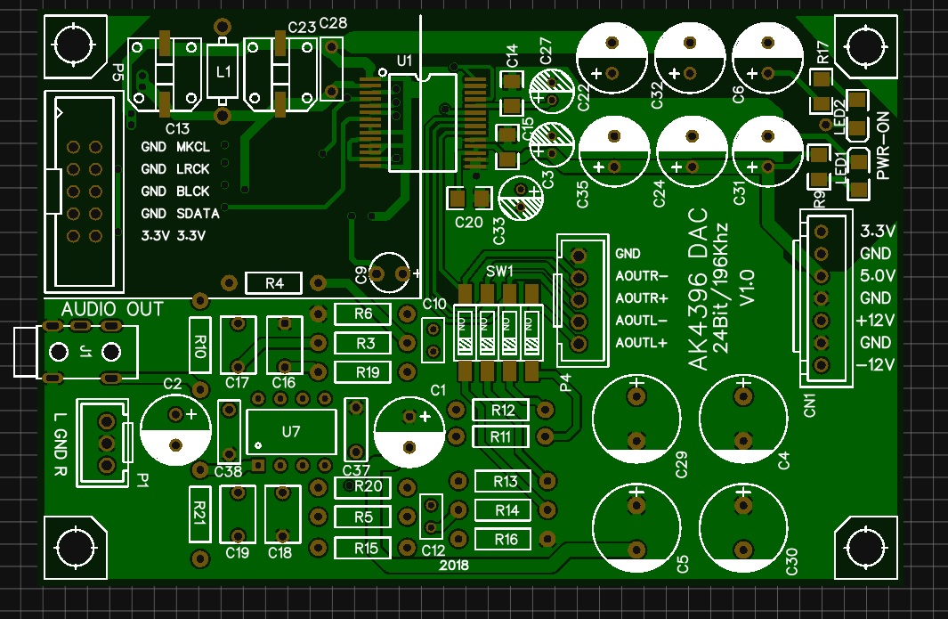
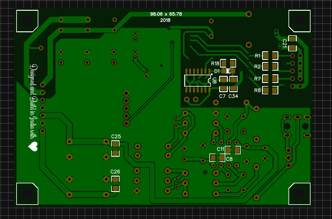
Here are some PCB updates.
Coupling cap c28 for digital is Panasonic OsCon 470uf 6.3v.
Digital rail caps c22,c32,c6 rail are Panasonic os-con 560uF x3 6.3v.
Coupling cap c33,c15 are 47uf and c27 is 10uf default this three are from nichicon.
As for dac analog rail caps c24,c31,c35 rail are Panasonic 560uF 6.3v.
For opamp coupling Panasonic 470uf and for opamp rail Panasonic 1000uf
Any suggestions...!
🙂🙂🙂🙂
Attachments

Any schematics? What regulators will you be using?
I am planning on adding a JL USB > I2S board to my still un-assembled AK4396 pcb.
For that I will have to design a small pcb, perhaps on a perforated proto-board, with the I2S connector to plug on the DAC and the I2S connector for the JL Sounds usb > I2S board, which is slightly cheaper than the DIYHink.
I2SoverUSB - I2S over USB Audio
As I said above, I plan to use a reed relay switch to select the internal or external input.
Does anyone know if the AK5393VS ADC runs warm to hot works OK
Have you found any evaluation board for the AK5393?
Any schematics? What regulators will you be using?
I am planning on adding a JL USB > I2S board to my still un-assembled AK4396 pcb.
For that I will have to design a small pcb, perhaps on a perforated proto-board, with the I2S connector to plug on the DAC and the I2S connector for the JL Sounds usb > I2S board, which is slightly cheaper than the DIYHink.
I2SoverUSB - I2S over USB Audio
As I said above, I plan to use a reed relay switch to select the internal or external input.
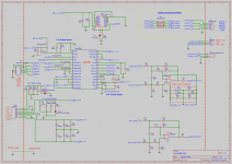
Here is the schematic
I am using a LM329DZ Voltage reference with LM4562MAX Opamp to drive a Mosfet for linear regulation
there are three for one for 3.3, one for 5v and one for both+-12
I think DIYHink CM6631A is best usb to i2s out there.
do you have any good discreet staging design..!
🙂🙂🙂🙂
Attachments
I am not sure what discrete stage would be best for this application. I would like to know too. I haven't seen any service manual with discrete CD output stages. Marantz used them, I think. The HDams discrete opamps.
As I said I do not have any specific discrete stages I prefer. But googling the Marantz HDam I found this comment about it and a very simple circuit suggestion;
Fet-ishizator
As you see, you can put two on DIP-8 socket.
Fet-ishizator
As you see, you can put two on DIP-8 socket.
with LM4562MAX Opamp to drive a Mosfet for linear regulation
Something resembling a Sulzer or Jung regulator?
As I said I do not have any specific discrete stages I prefer. But googling the Marantz HDam I found this comment about it and a very simple circuit suggestion;
Fet-ishizator
As you see, you can put two on DIP-8 socket.
why no try a discrete with tubes, we know it can be done without feedback with great results if properly done.
I should spend more time to do it. I am always glued to my vinyl rig 🙂
Today I built this DAC using Dario's BOM (CleveFremen). I had bought the materials a long time ago, and I finally got around to building it - jeej!
Right now, this is still a soldering workshop for me. I am an absolute beginner, but I am keen to learn. I'm reading the thread, but it's hard to understand everything. I'd like to learn more about audio circuits in general and in particular the troubleshooting.
I put the DAC together and lo and behold, the thing works! But before it worked I blew a capacitor. The effect: the right channel took a beating: without digital input I have a hiss only on the right channel, and with input the sound of the right channel is attenuated. The left channel sounds amazing 🙂
In post #95, CleveFremen posted a drawing of the pcb with labels for the components. It was C17, to the left of the opamp, that blew. Mind you, I had placed an Elna ROA (Cerafine) 47 uF 25V in it's place, under the assumption that black (ground) would be the negative pole on the capacitor. What's the reason that this assumption was wrong? I've now placed the default 100nF caps on C17 and C14.
I used the opamp that came with the circuit, and I think I destroyed the opamp (hopefully). I have OPA827's but without a browndog (I ordered it), so I can't test if my theory is right. Is it reasonable to believe I messed up the opamp, or would I have to look elsewhere for faults as well?
Before I plug in the more expensive opamps, is it necessary to place the NE5532 so I can test the results?
Last edited:
I always use something like a 5532 for testing until all is known to be good, keep the nicer op amps tucked away safely hidden from eager fingers, bad feedback circuits, overblown power supplies, shorted outputs, cold solder joints.
Thanks for your reply. I read that a smarter way of going about it would have been to just build the amp kit and make one upgrade a time. In any case I'm happy I've 'tested' it with a 5532 instead of the OPA827's.
But am I right in thinking that the fact I connected the cathode of C17 (a cerifine cap according to Darios BOM) to the ground was incorrect, because it's on the negative voltage rails - so in this case I should have connected the anode to ground?
But am I right in thinking that the fact I connected the cathode of C17 (a cerifine cap according to Darios BOM) to the ground was incorrect, because it's on the negative voltage rails - so in this case I should have connected the anode to ground?
Something resembling a Sulzer or Jung regulator?
yes smiler to it...!
I always use something like a 5532 for testing until all is known to be good, keep the nicer op amps tucked away safely hidden from eager fingers, bad feedback circuits, overblown power supplies, shorted outputs, cold solder joints.
I do the same thing 🙂
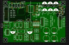
Hey everyone i am posting my current progress on this DAC board from testing and after listening it for a while, i have to say there is no for any equalizer at all. lows, mid-bass, mid, highs all are there perfectly. I loved this chips frequency response to every track genre perfectly well balanced.
For the op-amp i used LM4562NA op-amp but soon going to switch to discreet staging...!
Any suggestions....!
For the op-amp i used LM4562NA op-amp but soon going to switch to discreet staging...!
Any suggestions....!
Hey everyone i am posting my current progress on this DAC board from testing and after listening it for a while, i have to say there is no for any equalizer at all. lows, mid-bass, mid, highs all are there perfectly. I loved this chips frequency response to every track genre perfectly well balanced.
For the op-amp i used LM4562NA op-amp but soon going to switch to discreet staging...!
Any suggestions....!


Which DAC board is that? I thought we were talking about blue-pcb AKM4396 eBay project. This one is completely different.
What USB interface is that? What regulators are those?
What USB interface is that? What regulators are those?
- Home
- Source & Line
- Digital Line Level
- DAC 2496 (AK4393) DAC KIT With CS8416+AK4393+5532