Thank Ivan, i get it.. and you confirm that you use 10k pot volume with 100k ?There is no second pot. Its only one pot with three additional holes so that you can use either standard 16mm log pot or bigger ALPS RK27 log pot.
hicoco, check post #29 for an answer to that question. bear in mind that ivan uses a Log pot while the original schematic uses a linear pot.
So I'm still experimenting with the P88 and with the P06 phono stage.
I just realised that the P06 has 1uf coupling caps at the output and the P088 has 1uf cap at the input. May I assume that i could leave one of them out as I don't have to "double couple" the signal?
If I leave one out I'd prefer to leave the ones at the P06 output out so I can retain the ones on the input of the P88 as I have no idea what sources I'll connect to it in the future. If I leave the the output caps on the P06 out, do i still keep the 100k resistor (R9)?
An externally hosted image should be here but it was not working when we last tested it.
If you know for sure that you won't use P06 with some preamplifier that does not have high pass filter at the input, you don't need C5 1uF and R9 100k. Together they make high pass filter.
C1 and R1 at the input of p88 form the exact same filter, right?
P06 and P88 will live in the same enclosure so P06 will always be connected to P88. Thats why i want to keep the filter on the input of P88 because there will also be other sources connected to it.
newbie question: does the high pass at the output serve the same purpose as a coupling cap? so to keep dc out?
Yes, but coupling cap always has resistor to ground after it, it doesn't matter if it's input high pass filter or output high pass filter. They always go together. Cap + resistor = high pass filter that keeps DC out.
I will use 10k ALPS RK27 Dual, thank.Yes. But it's no problem if you use 20k log pot and 100k.
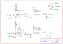
Here is schematic for my new P88 boards
Attachments
i believe the coupling cap should be 2x 1uF in paralell. you have a single 10uF cap. not sure if it would make a difference but the cap would probably be rather large.
I use this cap for in and outi believe the coupling cap should be 2x 1uF in paralell. you have a single 10uF cap. not sure if it would make a difference but the cap would probably be rather large.
Attachments
No. High pass filter means that the filter will pass all frequencies above few Hz (several Hz, 2, 3, 4, etc). The lower that Hz value is the filter is better. Filter consisting of series resistor and cap to ground would be low pass filter, it will pass only frequencies under some desired frequency. 1uF will give higher filtering frequency, 10uF will give lower filtering frequency
Both high pass filters in P88 and high pass filter at the output of P06 are intended to keep DC out but if you use higher cap value it will be more efficient (at the cost of PCB size, it will have to be bigger or you will have to put cap outside the PCB).
Both high pass filters in P88 and high pass filter at the output of P06 are intended to keep DC out but if you use higher cap value it will be more efficient (at the cost of PCB size, it will have to be bigger or you will have to put cap outside the PCB).
I believe that with the 2uF/100K combination cutoff will be at 0.8Hz and with 10uF cap it will be at 0.16.
The 10uf cap will be about the same size as all the other parts of the amplifier combined 🙂. But it will for sure look "high end". I personally like the look of the Mundorf Caps.
Have you read this? Capacitor Characteristics
If you scroll down the page chapter 5.0 talks about oversized caps.
The 10uf cap will be about the same size as all the other parts of the amplifier combined 🙂. But it will for sure look "high end". I personally like the look of the Mundorf Caps.
Have you read this? Capacitor Characteristics
If you scroll down the page chapter 5.0 talks about oversized caps.
With 10uf the cutoff frequency value is 159.15 mHz and with 2uf 795.77 mHz
Oh, my mistake. Your numbers are right. I did not see that "m" is small letter. Your calculations are right 0,15Hz and 0,79Hz. I think that there are some online calculators for these filters.
Last edited:
yep, I use this one. RC Low-pass Filter Design Tool - Result -
Ivan, when you say the ones with higher cap values will be more efficient. What do you mean by "efficient"?
Ivan, when you say the ones with higher cap values will be more efficient. What do you mean by "efficient"?
All high pass filters produce phase distortion but those with lower cutoff frequency will produce less of it meaning that the bass reproduction will be cleaner. It will cut only DC and leave low audio frequencies as clean as possible. But it is not necessary to use very expensive and huge cap like Mundorf. Less expensive and smaller will do the job just fine.
Mixi, i don't care about the look i just care about the result and Ivan is right it will be more powerful to keep DC out of the input AMP....Now you can use an other Cap brand if you like but 10uf it is better than 2uFI believe that with the 2uF/100K combination cutoff will be at 0.8Hz and with 10uF cap it will be at 0.16.
The 10uf cap will be about the same size as all the other parts of the amplifier combined 🙂. But it will for sure look "high end". I personally like the look of the Mundorf Caps.
Have you read this? Capacitor Characteristics
If you scroll down the page chapter 5.0 talks about oversized caps.
Last edited:
thanks for the explanation, ivan.
hicoco: I'm a fool good looking components myself 🙂 never hurts if they also look good. and i think the mundorf caps do look good. and, yeah probably you also have a point regarding performance.
hicoco: I'm a fool good looking components myself 🙂 never hurts if they also look good. and i think the mundorf caps do look good. and, yeah probably you also have a point regarding performance.
Hicoco, that's one hell of a schematic. Very professional, congrats!. Now show us the pcb when done😀
Regards
Prasi
Regards
Prasi
- Home
- Source & Line
- Analog Line Level
- Rod Elliot Project 88 question