An externally hosted image should be here but it was not working when we last tested it.
An externally hosted image should be here but it was not working when we last tested it.
An externally hosted image should be here but it was not working when we last tested it.
An externally hosted image should be here but it was not working when we last tested it.
I can't see any of the pictures!!! 
edit: Can you try uploading them as attachments?
edit: Can you try uploading them as attachments?
Attachments

Last edited:
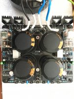
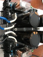
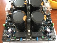
Thanks for the pictures.
Q1 and 2 seem to have their pins reversed. Remove them and solder 180deg flipped.
Q1 and 2 seem to have their pins reversed. Remove them and solder 180deg flipped.
thank !
yes, it was reversed
I put them back correctly, but nothing changes the relay does not connect
yes, it was reversed
I put them back correctly, but nothing changes the relay does not connect
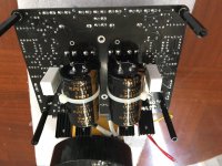
Please check Q1 and Q2 whether they were damaged during reversed operation. Just base-collector and base-emitter diode test will be sufficient. Can test without removing from board.
If Q1 and Q2 are fine then install one 10uF polarised electrolytic capacitor in parallel with the existing 10uF (C7 and C8). Turn on power and check (for 10-15 seconds).
edit: also check for any loose solder joint and whether all small transistors and resistors were placed correctly.
If Q1 and Q2 are fine then install one 10uF polarised electrolytic capacitor in parallel with the existing 10uF (C7 and C8). Turn on power and check (for 10-15 seconds).
edit: also check for any loose solder joint and whether all small transistors and resistors were placed correctly.
Last edited:
hi Shaan
all is well the relays works, I changed Q1 and Q2 and controlled the welts and small transistors
I am happy
thank you for your advice and patience
Henry🙂
all is well the relays works, I changed Q1 and Q2 and controlled the welts and small transistors
I am happy
thank you for your advice and patience
Henry🙂
hi Shaan
all is well the relays works, I changed Q1 and Q2 and controlled the welts and small transistors
I am happy
thank you for your advice and patience
Henry🙂
Glad I could help.
 🙂
🙂 
PSU GB2 List:
Vunce - 4 PCBs
Ejno -2 PCB
Brookhart995- 1 PCB
Rick G - 2 PCBs
Oracle1 - 2 PCB's
NishantS - 1PCB
Vunce - 4 PCBs
Ejno -2 PCB
Brookhart995- 1 PCB
Rick G - 2 PCBs
Oracle1 - 2 PCB's
NishantS - 1PCB
PSU GB2 List:
Ajit - 2PCB
Neurotica - 2 PCBs
amitskamal - 1 PCB+Components
Vunce - 4 PCBs
Ejno -2 PCB
Brookhart995- 1 PCB
Rick G - 2 PCBs
Oracle1 - 2 PCB's
NishantS - 1PCB
Adding back the folks from the original list at post 92.
Ajit - 2PCB
Neurotica - 2 PCBs
amitskamal - 1 PCB+Components
Vunce - 4 PCBs
Ejno -2 PCB
Brookhart995- 1 PCB
Rick G - 2 PCBs
Oracle1 - 2 PCB's
NishantS - 1PCB
Adding back the folks from the original list at post 92.
Adding back the folks from the original list at post 92.
PSU GB2 List:
Ajit - 2PCB
Neurotica - 2 PCBs
amitskamal - 1 PCB+Components
Vunce - 4 PCBs
Ejno -2 PCB
Brookhart995- 1 PCB
Rick G - 2 PCBs
Oracle1 - 2 PCB's
NishantS - 1PCB
I apologize, I didn’t mean to leave anybody out 🙁
As a matter of fact, this only helps our push for 50!!! I really like the features of this psu board and hope to use it for the V4 and other projects.
Hallo Shaan, i am going to use the psu pcb's for dual mono. After the crc more capacitance? How ? Is it necessary?
Hallo Shaan, i am going to use the psu pcb's for dual mono. After the crc more capacitance? How ? Is it necessary?
Because i have plenty of 10mf/63v.
Dual mono means each channel will have its own PSU. So IMO no need to install more than 4 of those caps. If used for Class-AB amps you can decrease the power resistors to 0.1R or just replace them with thick wires and have more transient current reserve in the PSU.
For the PeeCeeV4h dual mono 40mf per channel (20mf per rail) is good enough ? I wanted to hane 40mf per rail.
For the PeeCeeV4h dual mono 40mf per channel (20mf per rail) is good enough ? I wanted to hane 40mf per rail.
Sure! More capacitance per rail is always welcome.
One idea is to follow what Zebulo did - connecting them underboard. Check this post: Post 203.
Hi Shaan, I have read the description in the first page reagrding the size of the filtering caps, maximum 35mm? I am asking because I see on the pcb the two circles, I do not have the board with me now unfortunately. I was hoping that it would take also 40mm caps. To be more precise these from Kemet : ALC10C153EF063 - https://uk.farnell.com/kemet/alc10c153ef063/cap-alu-elec-15000uf-63v-snap/dp/9347941
Thanks.
Thanks.
- Home
- Group Buys
- PeeCeeBee PSU GB