The clue to this will be in careful voltage measurements.
I would begin by measuring the DC voltages on the transistors Q1, Q2 and Q3 when the reading has settled to a low point ? Measure on all 3 leads of each and record the result.
I would begin by measuring the DC voltages on the transistors Q1, Q2 and Q3 when the reading has settled to a low point ? Measure on all 3 leads of each and record the result.
From advice I've seen before you might get good mileage in terms of a response if you post some pics.
I will take some pictures and post them.
Ok...
So now i want to place a question that will make many laugh until fall on the ground....
I have ordered the chassis with frontal power switch. But now.... lol i think i can do the same assembly but just route the cables to the front power switch.
On another issue, in the build guide, step 44 means that i can use a XLR (no idea what that is...) but it retains the ability to play like a normal rca input stereo amp right? Having this make does not force me to use 2 amps right?
I don't understand your first question.
The second question answer is yes. you wire as the build guide and you can either use the switch to bridge the RCA input, or use XLR. If the switch is off, you have a stereo amp on RCAs
The second question answer is yes. you wire as the build guide and you can either use the switch to bridge the RCA input, or use XLR. If the switch is off, you have a stereo amp on RCAs
Got my v1.6 ACA kit yesterday and built it.
Made a mistake stuffing the board (I dont know how i did this, Im usually pretty good at not doing this). I managed to get R11 and R10 back to front in one channel, Obviously no sound came out. Once id tracked that down it worked quite happily.
However,
I am getting a temporary synth like zipper noise coming out of that channel. I think its only that channel.
It starts a couple of seconds after power on and lasts about a second. A bit like a low pitched whale, then stops and everything is fine, sounds great and both channels seem to be sounding the same.
Im wondering if ive damaged c3 with heat from a soldering iron. Im really hoping its not q4 because r10 connected to the gate should have been 332k not 10k. I would have thought if it was damaged it would break rather have an odd sound on start up as the circuit stabilises.
Any ideas what this might be? Because it doesnt last very long, tracking it down with a scope is likely to be a pain and involve switching on and off lots and lots so thats why ive posted here first.
Thanks
Mr. Dave45,
Remember the output is CAP COUPLED. That zipper sound might be the nearly 3.5MF cap charging up. That is normal. More easily heard on high sensitivity systems. There are ways to eliminate it like using even larger valued capacitors or more elegantly a circuit like the Guardian 86 from Neurochrome.
Best,
Anand.
Humming on startup have been noticed by quite a few builders. I wouldn't be too concerned although it is odd that only one side does, and this side matches the one where the resistors where switched.
Thanks, I did wonder if the output cap did take a while to charge. Ill have another listen, It more noticable out the left side but thats because the amps sitting on the left speaker at the moment!
Its had a few hours playing time and hasnt failed yet. Theres a little pop as i turn it off but again, I suspect thats the output cap emptying.
Ill get on and install my 12v trigger circuit so I can turn on and off from my new yamaha wxc50 preamp. It will automatically shut the amp off after 20 minutes on inactivity.
Really impressed with this little setup out of the box and no doubtit will improve over the next couple of weeks. I got it for the kitchen system and it drives my old mission 733i quite happily but tempted to build some troels gravesen 3way bookshelves for it as theyre a bit big and have to compete soundwise with the awesome obl15s in the lounge.
Thanks again
The clue to this will be in careful voltage measurements.
I would begin by measuring the DC voltages on the transistors Q1, Q2 and Q3 when the reading has settled to a low point ? Measure on all 3 leads of each and record the result.
Hi,
Here are my readings with the white knob in blue in straight up position:
Q1 Q2
Lead 1 .000 24.06
2 .089 24.09
3 ,555 .082
I don't understand your first question.
The second question answer is yes. you wire as the build guide and you can either use the switch to bridge the RCA input, or use XLR. If the switch is off, you have a stereo amp on RCAs
I will try my best to explain, please bare with a noob that had rudimentary electronics in school 25 years ago and never done anything since almost but some small soldering thingies. 🙂
So per 1.5 manual there is a switch on the top back of chassis that i think is to power on/off the amp. I ordered the chassis with frontal power switch (fail i know now...). So this means i will have to route the positive form the v in to the switch 1 leg in front and in the other leg the 2 v+?
This frontal switch is rated 10A@250vac.
Im confused now in a vale of noobish ignorance lol
fred0... think of it this way: you can configure the powering-up 'stage' of your AMP in two ways:
- Power switch on the back (which will be a cue-tip type switch)
- Power switch on the front (this is the nice rounded light-switch type)
If you ordered the frontal power switch, that means that the front panel will come with the 20mm hole already perforated in it to accommodate for the switch. If you wouldn't have, the front panel would have come without that round hole, and only the two LED ones.
With your choice, you will need to carry V+ from the PSU to the front switch (a twisted pair of cables as per the guide) and then connect the interrupted Voltage from the switch to each channel.
This is, IMHO, the nicest approach, and I did that myself... so I don't think it's a 'fail' on your side, unless you really wanted that front clean and to power the amp from the back.
Once you go the route of frontal switch, you have the choice to use the back switch as a RCA single-ended mono switch to make the amp work as a monoblock with one single RCA cable connected. This doubles the AMP power (and other minor side effects I won't discuss now) but you would require two AMPs to get stereo sound.
The XLR connector you mentioned before is the 3 leg round type of connector usually found in studio or show microphones (if you have ever seen one) and also for balanced interconnects between audio devices (and other uses I wont mention as well).
That can be put in without any effect on the characteristics of the AMP if you ever think you will build a second one to have two AMPs doing the stereo. For this balanced connection, you not only double the AMPs power, but you also get better THD (distortion numbers). So, this is the 'dream' setup for a user that has access to a balanced source.
Since you mentioned you don't even know what the XLR connector is, you probably don't have a balanced source (DAC, PRE, STREAMER, etc.) that can feed into a balanced monoblock, so you can just skip that and enjoy your Amp.
I hope this helps somehow, but maybe English not being my native tongue would mean that my post is more confusing than it is helpful.
Best regards,
Rafa.
fred0 - see http://www.diyaudio.com/forums/pass-labs/215392-amp-camp-amp-aca-508.html#post5509597
for more details. Back switch, is this case, is used for bridging with the RCA inputs. Front switch is used for power off/on.
for more details. Back switch, is this case, is used for bridging with the RCA inputs. Front switch is used for power off/on.
Last edited:
...I am getting a temporary synth like zipper noise coming out of that channel...
...Theres a little pop as i turn it off but again...
Mrdave, this mimics my setup to the letter! When you power it up, there is a very faint (only able to hear it with my ear pressed to the woofer of the speaker) that goes "ziiing". And then it idles to perfect silence.
I think this is the caps charging up.
And, when powering of, there is very clean: POP! that is even visible in the woofer as moving half an inch or so. But its clean, and not really loud.
I think you are perfectly fine with everything you are describing.
Enjoy the AMP!
Best regards,
Rafa.
Hi,
Here are my readings with the white knob in blue in straight up position:
Q1 Q2
Lead 1 .000 24.06
2 .089 24.09
3 ,555 .082
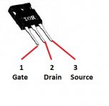
I'm assuming that by lead 1, 2 and 3 you are measuring left to right where 1 would be the Gate, 2 the Drain and 3 the Source.
If so, then this seems to show an issue around Q2 which appears to be non conducting. Are you measuring directly on the transistor pins ?
It would be pretty unusual for a power FET to fail like that but the reading on the face of it does show an issue.
Attachments
Sorry about that presentation. It is not the way I typed them. Hope this will be easier to read:
Q1 Lead 1 .000v
2 .089
3 .555
Q2 Lead 1 24.06v Lead 2 24.09v Lead 3 .082v
Q1 Lead 1 .000v
2 .089
3 .555
Q2 Lead 1 24.06v Lead 2 24.09v Lead 3 .082v
🙂 No problem.
I think I followed it right at first, you have 24 volts on the Gate (1) and 24v on the Drain (2) but the Source (3) is at almost zero. That points to Q2 intrinsically being non conducting (open circuit).
A 24 volt differential between G and S should turn the FET fully on. If you have those voltages on the actual pins of the device (measuring on the pins removes doubt over open print anywhere) then the FET at least appears to be dead.
Did you obtain the parts yourself from various places ?
With that picture the readings should be:
Q1 Lead 1 .555v Lead 2 .089 Lead 3 .000v
Q2 Lead 1 .082v Lead 2 24.09v Lead 3 24.06v
If it is the way the transistor is screwed to the heat sink which I assume it is. Thanks
Q1 Lead 1 .555v Lead 2 .089 Lead 3 .000v
Q2 Lead 1 .082v Lead 2 24.09v Lead 3 24.06v
If it is the way the transistor is screwed to the heat sink which I assume it is. Thanks
Well, first of all i am grateful of your reply as i just learned some new things that before were like dark magic to me. But i still need to search and learn what balanced input is...
In fact i have a pre amplifier here that i was under the impression i would have to use to feed the amp. But i have no education on balanced inputs and things like that.
The pre i have is a sony ta-e1000esd that i bought 2 years ago just because i got an amplifier that required it and got the pre for cheap.
It does thousand things but i just really use it to feed that amp... i dont know nothing about all those magic things the pre does...
As for the amp and power switch you are right i got the one with the round power switch in the front and now i noticed the instructions for 1.5 kit dont use it. That is why i got stranded here... no idea on what to do.
Routing the power v+ in to the front switch is no issue as it ends up being the same as in the picture, but using the back one to toggle from stereo to monoblock is still beyond my understanding...
- Home
- Amplifiers
- Pass Labs
- Amp Camp Amp - ACA