I understand what the cascoding accomplishes in First Watt clones where implemented, but am not sure how they are calculated. I do notice that they are different for various different amps.
This question asked, there may be no answer that is usable by me if it involves unusual calculation requiring skills beyond my reach, but if there is a formula I may be able to find a way via the internet to perform said calculation.
Next difficulty may be that I lack requisite equipment to measure certain parameters required for the calculation.
Perhaps if there is a way to get "close" then measure the result and making adjustments I can still get there?
The only amp I have started that had Cascode was a F5 Turbo kit that I never finished and sold electing to build BA3 power amp instead. That amp does use a 24 + 24 volt transformer, which results in 30 volt rails. The amp's Jfets have tolerated this well, but being close to the danger zone I have always wished to graft on a cascode to alleviate this worry. Plus, I have been wondering about this calculation for some while.
Thanks for any help, assuming any is possible,
Russellc
Last edited:
I'm on the beach now,will post later from home. It's simpler and easier than you think
Great, glad to hear that. Enjoy the Beach!
Russellc
first you need to read Papa's article : http://www.firstwatt.com/pdf/art_cas_amp.pdf
then you can prolong enjoyment reading http://www.firstwatt.com/pdf/art_sweet_spot.pdf
usually there is a need for defining/limiting working voltage for some part ; what will be that voltage can be decided based on various reasons (limiting dissipation , finding sweet spot while taking care of dissipation , disabling Miller effect etc. but all these can be taught on higher level and certainly from someone more clever than Mighty Moi 🙂
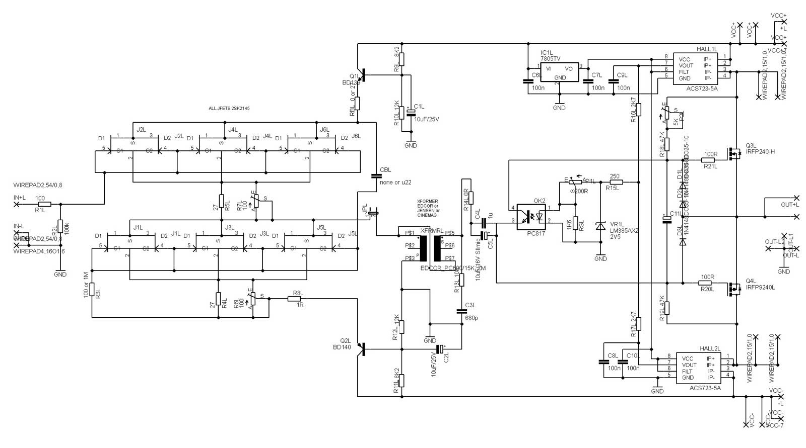
now - see enclosed pic , observe just upper JFets in input buffer ;
I had idea to act as Mighty Tailor Mickey , to swish few flies with one stroke , so decided to limit PSU voltage for little buggers
I chose something as +12V, that with chose Iq per one JFet (21mA/6pcs) is giving approx. 42mW per one , or 84mW per case (having two in parallel)
my general rails are in range of 22V5 (18Vac secondaries , mult. with 1.25)
so , decent BJT is good for that role , even if I could use IRF510 with same results
let's use old but trusty BD139
if I make voltage divider from rail to gnd , letting through approx. 1mA , I'll have enough current for divider itself and for bjt base current
calculating these resistors is hit and miss procedure , but with time one is more and more successful in doing that
so , from these and some other reasons I chose 8K2 up and 12K down
our voltage divider will have voltage level in middle point calculated as 22V5/(8K2+12K) x 12K=13V36
if we connect bjt base there , while we know that emiter of NPN bjt is always 0V65 (one diode drop) lower than base , so we'll have 13V36-0V65=12V74
then we just need to filter a little that voltage divider node , to prevent it from any jumping with bass notes ( draining main caps ) , so we just put adequate cap acros lower resistor , calculated for low frequency (2-5Hz) with simple formula F=1/(2 x Pi x R x C)
that's it
NB that proper and real cascode is actually having voltage divider/string/whatever connected to JFet's source , so shielded part is actually working in constant voltage mode ; that demands much more careful planning of currents involved ( in voltage biasing) , to prevent influence on current path of shielded device
this one is more like voltage divider , voltage umbrella or whatever it can be called , but action is pretty close to modulated cascode ...... even if sorta backwards . because jumping of gate-source end of JFet is actually shorting Uds for same amount
shoot if you need more
then you can prolong enjoyment reading http://www.firstwatt.com/pdf/art_sweet_spot.pdf
usually there is a need for defining/limiting working voltage for some part ; what will be that voltage can be decided based on various reasons (limiting dissipation , finding sweet spot while taking care of dissipation , disabling Miller effect etc. but all these can be taught on higher level and certainly from someone more clever than Mighty Moi 🙂
now - see enclosed pic , observe just upper JFets in input buffer ;
I had idea to act as Mighty Tailor Mickey , to swish few flies with one stroke , so decided to limit PSU voltage for little buggers
I chose something as +12V, that with chose Iq per one JFet (21mA/6pcs) is giving approx. 42mW per one , or 84mW per case (having two in parallel)
my general rails are in range of 22V5 (18Vac secondaries , mult. with 1.25)
so , decent BJT is good for that role , even if I could use IRF510 with same results
let's use old but trusty BD139
if I make voltage divider from rail to gnd , letting through approx. 1mA , I'll have enough current for divider itself and for bjt base current
calculating these resistors is hit and miss procedure , but with time one is more and more successful in doing that
so , from these and some other reasons I chose 8K2 up and 12K down
our voltage divider will have voltage level in middle point calculated as 22V5/(8K2+12K) x 12K=13V36
if we connect bjt base there , while we know that emiter of NPN bjt is always 0V65 (one diode drop) lower than base , so we'll have 13V36-0V65=12V74
then we just need to filter a little that voltage divider node , to prevent it from any jumping with bass notes ( draining main caps ) , so we just put adequate cap acros lower resistor , calculated for low frequency (2-5Hz) with simple formula F=1/(2 x Pi x R x C)
that's it
NB that proper and real cascode is actually having voltage divider/string/whatever connected to JFet's source , so shielded part is actually working in constant voltage mode ; that demands much more careful planning of currents involved ( in voltage biasing) , to prevent influence on current path of shielded device
this one is more like voltage divider , voltage umbrella or whatever it can be called , but action is pretty close to modulated cascode ...... even if sorta backwards . because jumping of gate-source end of JFet is actually shorting Uds for same amount
shoot if you need more
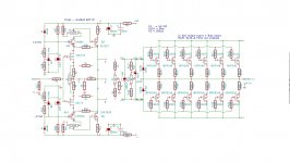
what I'm writing about in penultimate paragraph - see this schm , to be clearer
switches for plain voltage umbrella and proper cascode
some calling it Hawksford cascode , but origin is older than Hawksford articles , at least for my knowledge
that one (shielded device having real constant voltage modus operandi) you are going to use if you want to kill Herr Miller for good, which is obviously correct and actual only for stages having gain ........ as first stage of ONO, XONO, Pearl , etc.
picture origin is from here , but can't remember whom to credit
Attachments


Still reading articles, although not on beach...my purposes for cascoding is simple, just to protect Toshiba J fets when rail voltage is high enough to cause fear of destruction. I understand the breakdown for Toshiba as used in First Watt amps is around 40 volts, but mid 30s I figure to reduce life expectancy.
Haven't fully grasped sweet spot idea, I'm just wanting to protect jfets from high voltage rails, like in F5 turbo. Reading on.
Russellc
Haven't fully grasped sweet spot idea, I'm just wanting to protect jfets from high voltage rails, like in F5 turbo. Reading on.
Russellc
Last edited:
- Status
- Not open for further replies.
- Home
- Amplifiers
- Pass Labs
- calculation of cascode components