Thanks to TI they sent me free samples of OPA1622.
And I solder it on my PCB converter and put it in the FiiO X3-1 output amplifier. It works great! Exellent sound! The best amplifier!


And I solder it on my PCB converter and put it in the FiiO X3-1 output amplifier. It works great! Exellent sound! The best amplifier!
Hi Johnc,
I read the datasheet thoroughly and quite confused at how to calculate the output noise:

In the non-inverting configuration, why only current noise of R2 is calculated? Isn't current noise of R1 is (R1*In)^2? I have read some text book about opamp noise and the thermal noise of feedback resistor is calculated as R1//R2*(1+R2/R1), i don't think it match e1^2+e2^2 here.
Thanks!
I read the datasheet thoroughly and quite confused at how to calculate the output noise:
In the non-inverting configuration, why only current noise of R2 is calculated? Isn't current noise of R1 is (R1*In)^2? I have read some text book about opamp noise and the thermal noise of feedback resistor is calculated as R1//R2*(1+R2/R1), i don't think it match e1^2+e2^2 here.
Thanks!
Yep, you're correct. This section was repeated from other datasheets and the error was just recently brought to my attention (I didn't write it).
Current noise from the op amp input flows through the effective impedance of the feedback network which is the parallel combination of R1 and R2.
Current noise from the op amp input flows through the effective impedance of the feedback network which is the parallel combination of R1 and R2.
John, I can now confirm that putting four OPA1622 op amps in parallell works like a dream! When driving 300 Ω Sennheiser HD650, it sounds wonderful. The old version with 2 output driver struggled a bit with high gain, but with four it's working perfectly. Who knew that the HD650 could handle base so well.
John, I can now confirm that putting four OPA1622 op amps in parallell works like a dream! When driving 300 Ω Sennheiser HD650, it sounds wonderful. The old version with 2 output driver struggled a bit with high gain, but with four it's working perfectly. Who knew that the HD650 could handle base so well.
An externally hosted image should be here but it was not working when we last tested it.
Four in parallel?! That thing is a beast! Cool project 😎
Hi John,
I have made an headphone amplifier using the opa1622, it work fine but doesn't sound very great. I have some other portable amps as reference: jds c5d, cayin c5, o2. Although i think i can hear more detail with my opa1622, its soundstage is quite closed in, not as spacious as the amp i mentioned above, i think it also lack dynamic and sounds a bit soft.
I measure it using the qa400 and it's the best measured amp in line with the o2: only 0.0008% thd at 400mv@32R but doesn't sound convincing enough.
Here is the schematic and layout, can you take a look and see if i can do anything to improve it? Parts value i used:R1/R3 220, R2/R4 10k, R5/R6 1.5k, R7/R8 1k, C1/C2 1uf/x7r, C5/C6 10uf tantalum, C3/C4 220pf, R9/R10 short, volume pot 10k, power supply using 2 9v decoupling by 220uf capacitor. With the above component i got about 1mv dc offset at ouput.


As i didn't have good result with the opa1622 but i'm still curious, i have ordered the evaluation board and man, it does sound so good, much better than my board. I tried to match the component value of two boards, different brand but i use 0.5% resistor, c0g capacitor for Cf and x7r for power supply capacitor so i think it's all fine but nothing change, the eva board still sound much better. I don't think the problem come from my layout either, i think it's already optimizied: signal gnd, power gnd and output gnd is seperate and join at ps gnd, no gnd plane under inverting input of opamp to prevent parasitic capacitance. I also have another board which is almost the same as the previous but have a continuous gnd plane and it sound slightly worse. So i think that the problem might come from pcb quality. My pcb is fab from a chinese store, it cost only 10$ for 10boards of 10x10, the pcb look neat, clean, there is no discontinuous or anything bad about it but have you ever had some problem like mine that actually come from the pcb quality?
Do you have the tools to look for oscillations? You have a ground plane split that may be an issue at RF frequencies. A quick check would be to bridge across the ground plane at several places and see if it makes a difference.
Hi guys.
Could you help me?
I'm going to build a amp based on few OPA1622 and I've got two questions on my mind.
Should I include output resistors for every OPA1622 output? They will work as a pure buffer (G=1) and should I include those resistors in-loop or out-of-loop?
Because both method will work properly 🙂
BTW should I remove copper layer from IN/OUT pin in my PCB? Many hi speed boards are done this way, but when I was looking at OPA1622EVM i saw that there is no cutouts at 2nd layer (it's two layer board).
So maybe that IC will not suffer from stray capacitance?
Last edited:
I found this thread by coincidence. OPA 1622 is still the newest flagship op amp of TI, isn't it? Since I am not DIY'er and have no idea how to create own thing, Could anyone suggest me what final products using OPA1622 or can be replacable with OPA1622 and bring astounding sound?
I'm interested on 2.5 mm. balanced USB DAC/AMP (without battery is preferable likes MIYO, Space Plus which are kickstarter crowd-funding campaign products)
I'm interested on 2.5 mm. balanced USB DAC/AMP (without battery is preferable likes MIYO, Space Plus which are kickstarter crowd-funding campaign products)
Thanks to TI they sent me free samples of OPA1622.
And I solder it on my PCB converter and put it in the FiiO X3-1 output amplifier. It works great! Exellent sound! The best amplifier!
View attachment 607792
View attachment 607793
Hi plutonim, your adapter is exactly what i've been searching for to mod mi Fiio X1. Outstanding work, are they available for sale? I'm in the UK, thanks.
At the risk of making me unpopular. I think the chip is totally unsuitable to build a professional headphone amplifier. The output power is simply too small to handle complex headphone loads. The power dissipation is limited by the small chip area, and the distortions become too great. This chip certainly has its existence in small mobile devices (smartphone, MP3 players, etc.), but not in the stationary hifi area.
Last edited:
Maybe you can define the complex headphone load and the sensitivity of the headphone that make this solution unacceptable?
First (beta) customer
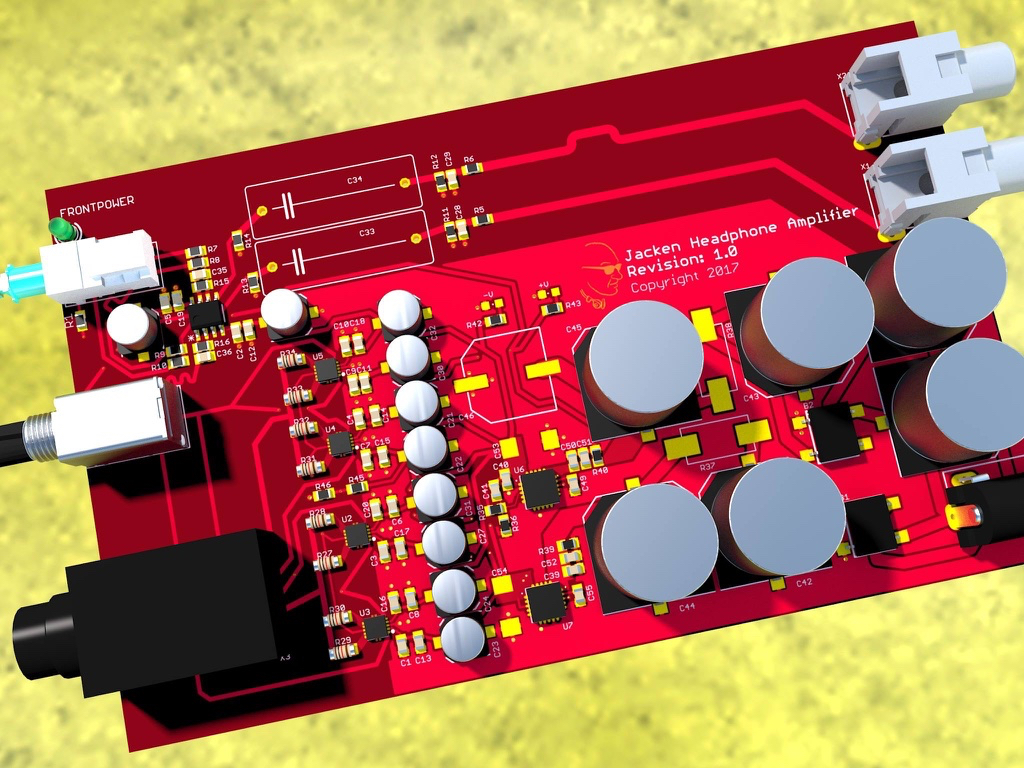
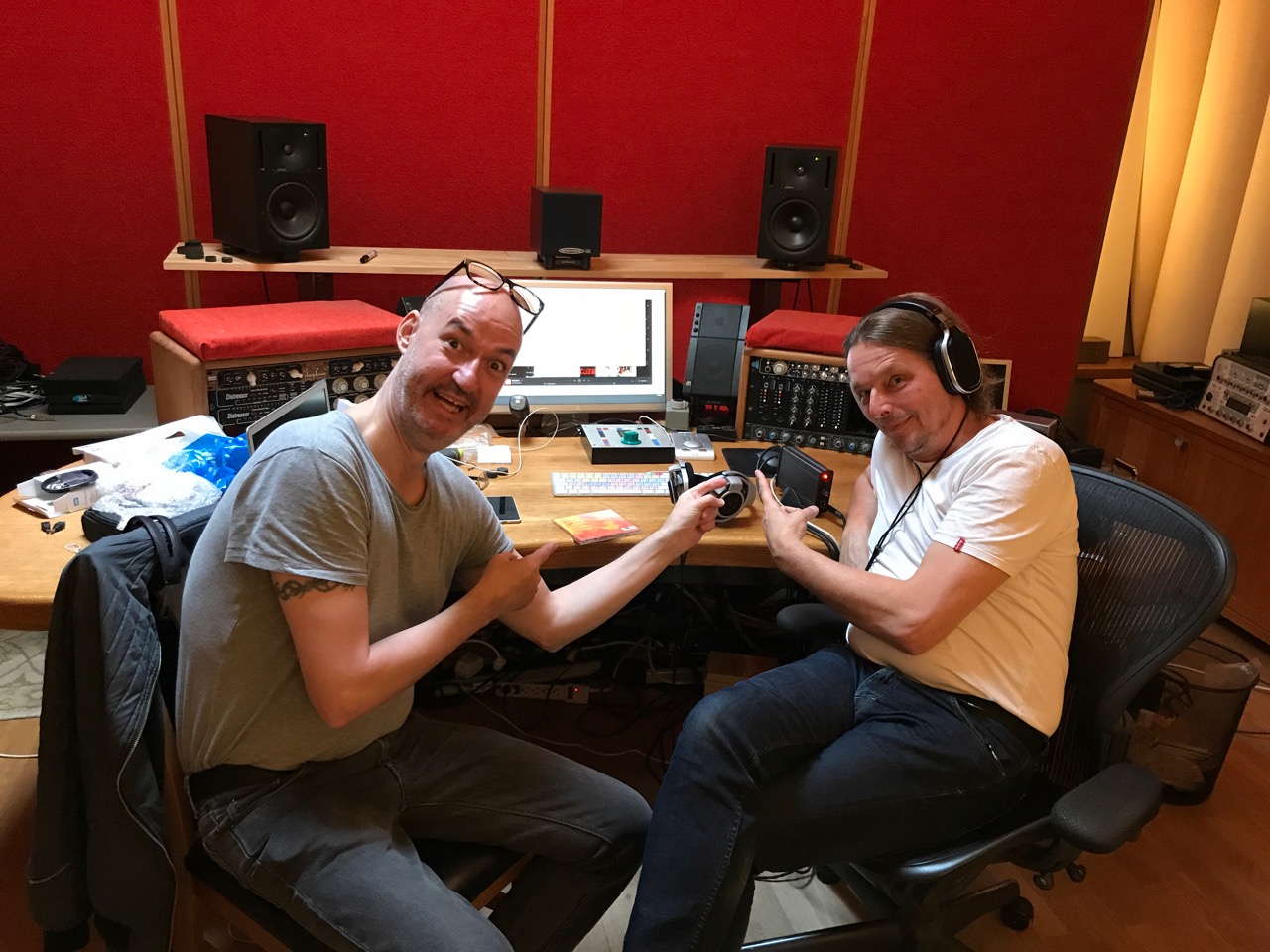
After a lot of different designs, I've finally completed my headphone amplifier with four OPA1622 summoned as output op amps. First beta-tester, Rammsteins producer Jacob Hellner! He tried three different DACs and spent an hour testing and decided to include my amp in his mixing chain. Very proud.
Hopefully I can make it to production, because now I'm building them by hand which takes a long time with almost everything in SMD.
Anyone that says that the Sennheiser HD-800S doesn't do bass, haven't tried my amplifier 🙂
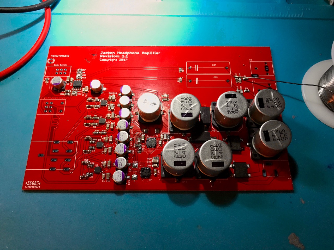
Here's an amplifier directly out of the reflow oven. Needs an ultrasonic bath obviously.
After a lot of different designs, I've finally completed my headphone amplifier with four OPA1622 summoned as output op amps. First beta-tester, Rammsteins producer Jacob Hellner! He tried three different DACs and spent an hour testing and decided to include my amp in his mixing chain. Very proud.
Hopefully I can make it to production, because now I'm building them by hand which takes a long time with almost everything in SMD.
Anyone that says that the Sennheiser HD-800S doesn't do bass, haven't tried my amplifier 🙂
Here's an amplifier directly out of the reflow oven. Needs an ultrasonic bath obviously.
A lot of people are using this part to drive headphone directly, I have only one question, will this sound as good as reported if I use it with the LME49600?
It is not a general purpose opamp but an amp designed to drive headphone. So, within it's specs, there's no need to use a buffer such as LME49600. And if you want to build a two parts headamp with an opamp and a buffer don't use OPA1622 as opamp but general purpose audio opamp.
Yeah it seems TI's intent was to replace the LME49600 with the OPA1622 (they almost killed the LME49600 but relented 🙁), under the belief that the majority of headphones don't really need 250mA of current capability. For those of us who disagree you can parallel them, like jacken's creation above. The OPA1622 really is a fine chip. johnc124 did a great job with it, IMHO. 🙂
The application circuit in the datasheet and the related app note TIDUAW1 both show a very simple first order low-pass with a rather distant pole at 416.6kHz.
Don't DACs need a reconstruction filter with significant rolloff at the sampling frequency to avoid aliasing / imaging of high frequency components into the audible band? It doesn't seem like a filter with such a high corner frequency can meet that goal, but I trust that @johnc124 knows more about this than I do!
(Thoughts: Since we know that the following stage is a pair of headphones, and the headphones have significant inductance, perhaps it just doesn't matter the way it would if the following stage were another active component?)
The application circuit in the datasheet and the related app note TIDUAW1 both show a very simple first order low-pass with a rather distant pole at 416.6kHz.
Don't DACs need a reconstruction filter with significant rolloff at the sampling frequency to avoid aliasing / imaging of high frequency components into the audible band? It doesn't seem like a filter with such a high corner frequency can meet that goal, but I trust that @johnc124 knows more about this than I do!
(Thoughts: Since we know that the following stage is a pair of headphones, and the headphones have significant inductance, perhaps it just doesn't matter the way it would if the following stage were another active component?)
Since most audio DACs are delta-sigma architectures, there is significant out of band noise above the audio frequency. High order delta sigma modulators have this useful "noise shaping effect". That noise is usually well above the audible frequency range, but if you want to implement a steeper filter slope to remove the out of band noise that's definitely an option. There are some examples in the PCM1792/3/4 datasheets of this. But be aware that there are usually some tradeoffs with THD+N performance due to the higher noise gain in an active filter circuit.
One a different topic, if you don't want to spend your hard-earned money on decent thin film resistors, check out the INA1620 we just released. We added matched resistor arrays to the die, pinned out and unconnected to the op amp, that you can use to build circuits to your heart's content. This was one of the last parts I worked on before taking a new role and moving to another group. My swan song product should hit the market later in the year...stay tuned 😉
- Home
- Vendor's Bazaar
- New Audio Op Amp - OPA1622