Mark, thank you for the cap info - very interesting file.
Regarding clock - you took the CCHD 575-50-100 clock. There is a CCHD 575x-25-100 clock available with lower ppm (25 instead of 50) and wider temp. range. Does it make a difference in Sound Performance at room-temp.? - Price is only 2 USD higher for the x - model..
PPM is not that important for DACs ic. Phase noise is what you need to look at.
Regarding clock - you took the CCHD 575-50-100 clock. There is a CCHD 575x-25-100 clock available with lower ppm (25 instead of 50) and wider temp. range. Does it make a difference in Sound Performance at room-temp.?
I wouldn't expect an audible difference on that factor. Then again $2 isn't much cost difference. Either one would probably be fine.
Regarding ways of mounting the clock, I cut away some top layer ground area to make a little more clearance around the clock solder pads. An argument for soldering the clock directly against the board is that clocks can sometimes be affected by vibration, and right against the board should probably be lower vibration than hanging from some wires.
Then again, soldering with some short wires which allow the clock to sit slightly above the PCB might be easier. If trying that method it might help to use, say, unleaded solder to solder the wires to the board solder pads, and then use leaded 63/37 solder to connect the short wires to the clock itself. The melting temperature differences between the two types of solder should help prevent the wires from coming loose during soldering if the higher temp solder is used first, and the lower temp solder used for the second set of joints. This assuming of course that the solder iron temp is set to the minimum melting temp for use with each type of solder.
EDIT: Looks like I cross-posted with cdsgames.
We are using the same NDK clocks (2x) they are very good....but one thing needs to be improved. If you look at the output of the oscilators the rise/fall time is long. A good buffer with its own clean power has to be installed between the DAC ic and clocks and it improves significantly the rise/fall time (make sure the additive phase noise of buffer is insignificant ). That is important for jitter as seen by the DAC ic (research white papers on rise/fall time affecting jitter on receiving side).
Thank you for this info cdsgames! This could explain the low effect in sound improvement (I expected more effect here due to my experience of introducing your Kali reclocker into my system and the improvement it did to my chain was much bigger..).
I am not willed (not able) to add another buffer circuit on my DAC board, so I think I will try the crystek clock instead.. But logistic costs of mouser in Germany are very high (below 50 Eur it is 20 EUR)... lets see if I Need some other parts from there or I find another source...
Very comprehensive features at excellent price. They quote 123DB S/N.
Does it have an I/V interface amp?
One of the SMD opamp is shown to be a OP275G. Looks like that there are 3 IC with a total of 6 opamps. I/V output is likely.Looks like it has more output stage opamps that just one, maybe 2 or 3. That could be enough for possible I/V conversion. Need to see better pics or see one in person to know for sure.
Can you tell the oscillator that they use? Is it a good one?
Is it a good one?
Well, I couldn't resist, so one is on order. For my next project I think I will go through one of the new DAC boards and see what I find that needs modding. I will let you know more when it gets here and I can take a good, close look at it.
I like the MShow DAC I bought last month fine. But this new DAC seems like a better value for not having to add the I/V stage. I already have LDO single ended linear power supply. I may get it if I can sell my current one for $100.Well, I couldn't resist, so one is on order. For my next project I think I will go through one of the new DAC boards and see what I find that needs modding. I will let you know more when it gets here and I can take a good, close look at it.
NEW ES9038 ES9038Q2M DAC HIFI Decoder AUDIO IIS DSD DOP 384KHz + Amanero USB | eBay

Mark, no need to excuse for anything! Not sure why the new clock did not bring a big improvement in bass - or can it be that the new KEMET polymer caps changed the bass performance into this more softer charakter? The caps are described not to be used for leakage current sensitive applications.....would tantal probably be better?
Babolcs,
the circuit in the post 1294 is what I finally use. It automatically sets the DAC into current mode. Nothing else to do to achieve that.. The left part of the circuit is on the bottom side on a seperate board while the right part was applied on the top side by modifying the existing circuit (replacing all components). What you dont see on the pictures are the vertical 6K8 resistors where the outputs of bottom board are connected to the circuit on the top side..Also be aware of the exact polarity of the opamp inputs. Pls ask if you have any further questions.
Thanks a lot. I will Analyse deeper for myself. In case of Any questions i will come back to you.
I am very tempted too. If the clock is good enough, the only mod required will be a good quality linear power supply. I sent one of the seller the following questions, but did not get the answer yet. Anybody knows?Well, I couldn't resist, so one is on order. For my next project I think I will go through one of the new DAC boards and see what I find that needs modding. I will let you know more when it gets here and I can take a good, close look at it.
1. How does it select among COAX / OPT / USB inputs? Only one volume knob on front panel.
2. What is the range in dB of the volume control?
3. Is it compatible with Apple Remote for input and volume control?
HiFi ES9038Q2M DAC Bluetooth 5.0 USB XMOS Audio Decoder Stereo DSD512 APTX HD 358962404740 | eBay
Keilau, I think they used a rotary encoder like the one on my 1.07 board. When I push it in it switches inputs.
I've looked at the pictures in that ebay link and to me it seems like the Sabre dac chip is run of a single ams type 3.3V ldo regulator. If that's the case the SNR 123db quote is just pure fiction! The best dacs have a high end ldo or op amp type voltage regulator circuit feeding dac, clock and output op amps. They've cheaped out on the most important aspect of getting good sound from the Sabre chip. Really too bad since it had lots of features..
I've looked at the pictures in that ebay link and to me it seems like the Sabre dac chip is run of a single ams type 3.3V ldo regulator. If that's the case the SNR 123db quote is just pure fiction! The best dacs have a high end ldo or op amp type voltage regulator circuit feeding dac, clock and output op amps. They've cheaped out on the most important aspect of getting good sound from the Sabre chip. Really too bad since it had lots of features..
PSU on latest ES9038Q2M box

I hope that this box is Apple Remote compatible like the MiniShaw box that I have. Markw4 has one on order. We will hear more about it soon. In fact, I am seriously considering ordering one myself.
Agree, I will take the "SNR 123db quote" with a grain of salt. On the question of PSU, which part are you talking about?Keilau, I think they used a rotary encoder like the one on my 1.07 board. When I push it in it switches inputs.
I've looked at the pictures in that ebay link and to me it seems like the Sabre dac chip is run of a single ams type 3.3V ldo regulator. If that's the case the SNR 123db quote is just pure fiction! The best dacs have a high end ldo or op amp type voltage regulator circuit feeding dac, clock and output op amps. They've cheaped out on the most important aspect of getting good sound from the Sabre chip. Really too bad since it had lots of features..
I hope that this box is Apple Remote compatible like the MiniShaw box that I have. Markw4 has one on order. We will hear more about it soon. In fact, I am seriously considering ordering one myself.
Last edited:
MHz frequencies probably aren't the big concern for AVCC, or ESS would have used more HF decoupling on AVCC for their reference designs.
More likely the resistance and noise pick up in long PCB traces would be more of concern.
In any case, if the new board uses AMS regulators for AVCC then we probably have an easy place to mod in order to improve SQ.
More likely the resistance and noise pick up in long PCB traces would be more of concern.
In any case, if the new board uses AMS regulators for AVCC then we probably have an easy place to mod in order to improve SQ.
Another user here on the forum reported that current into a dac were drawn at Mhz frequencies, the clock is after all 100Mhz. If decoupling could to a good enough job why would they bother with regulators at all? I think for practical and economic reasons they use caps. This is a high frequency appliance so why not design the circuitry as a high frequency switcher? A lot of people are in class ab mindset and I think the class D mindset would take us further. My plan is to put 2 regulators within 6-7mm of the chip and a wide ceramic even closer for decoupling. The trace itself will hopefully be less than 2cm long between regulator and chip leg.
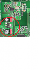
The cutout is from the last eBay link and it doesn't look like there much room for adding several voltage regulator circuits.
The cutout is from the last eBay link and it doesn't look like there much room for adding several voltage regulator circuits.
VCCA is a supply for analog circuitry and it should be decoupled at HF and on a clean regulator. AVCC is a different thing. If we had all the test equipment places like ESS and Benchmark have we could look with a spectrum analyzer and figure out the transfer function from AVCC to the DAC outputs. ESS is also in a good position since they design the chips. Since we are not doing all our own measurements we can probably learn or deduce some things from people that have done them. No sense in wasting energy speculating about stuff there is not really any evidence for. I have an ES9038Q2M data sheet and have carefully studied everything ESS has released. At this point there is no particular reason to suspect that RF decoupling of AVCC is likely to be useful. Of course we could get really crazy and impedance match it with tuned wave guide stubs, but there just isn't any reason to think it would help.
Also, I should probably mention that I have looked at the DAC outputs and IV outputs with a 100MHz scope. I can see down to as little as around 500 micro-volts, maybe a little less. I don't see any RF at the outputs. If there is any, and there very well might be some, there probably is, it is small and within the capability of the opamps to tolerate and still produce distortion down at -120dB THD, and -122dB noise. That is, if everything we do we do just right. If we get lax about the stuff we already know we should be paying attention to, then we can be sure we will make things worse.
Also, I should probably mention that I have looked at the DAC outputs and IV outputs with a 100MHz scope. I can see down to as little as around 500 micro-volts, maybe a little less. I don't see any RF at the outputs. If there is any, and there very well might be some, there probably is, it is small and within the capability of the opamps to tolerate and still produce distortion down at -120dB THD, and -122dB noise. That is, if everything we do we do just right. If we get lax about the stuff we already know we should be paying attention to, then we can be sure we will make things worse.
Last edited:
I am not knowledgeable enough to tell the quality of this PSU design. The Pro-Ject Pre Box S2 (a name brand ES9038Q2M box) credited their low noise result to their use of the ES9311 regulator by Sabre ESS Technology. Does this look like the ES9311 to you? If not, what it may be?To me it looks like the sabre chip is the one in my cut out picture. The ldo closest looks like an ams type to me. Having regulator more than 2cm away is not good for Mhz frequencies so I assumed they used the one closest.
http://www.box-designs.com/inhalt/en/pdf/preboxs2digital.pdf
Last edited:
Without any demo-board schematic to go with 123db claims, no one knows how that number ever came to be, is pretty meaningless imo.
I have had some great luck with an ams1117 3.3v reg lately, using a nichicon VX 100uf 25v as an output/damping. This was for a digital supply, and was the third and final regulator after lm7808, 7805.
Those nichicon vx were sold at radio shack, so had a couple left over from something, see that they are discontinued now.
At this pricepoint I just assumed they used a ams1117 3.3v and that will not give anything near a 123db SNR. Not even a LT3045 (a better LDO) will give us that good signal to noise ratio. I think it was Mark that pointed that out earlier in this tread.. But if you change out that regulator that Dac could otherwise turn out to be a little gem 🙂
We are using the same NDK clocks (2x) they are very good....but one thing needs to be improved. If you look at the output of the oscilators the rise/fall time is long. A good buffer with its own clean power has to be installed between the DAC ic and clocks and it improves significantly the rise/fall time (make sure the additive phase noise of buffer is insignificant ). That is important for jitter as seen by the DAC ic (research white papers on rise/fall time affecting jitter on receiving side).
I have seen this mentioned elsewhere and perhaps should not be dismissed so quickly. Since you've worked *extensively* with these chips, what kind of buffer would you recommend or use as an example? Perhaps it would not be that hard to implement.
Lots of equipment will benefit from a better power supply!
When I first saw this board it looked as if it didn’t have any onboard regulation, I was looking for something with a heat sink. I’ll bet if you were to pre regulate before the board the ams on the board would work much better, and still be a reasonably priced solution, less hacking.
Usually the small ceramic bypasses are for the high frequencies, not so much the reg itself.
- Home
- Source & Line
- Digital Line Level
- ES9038Q2M Board