Hello to all,
I did not know this evolution of tpa3116 that I was about to buy back.
I have a pair of 6 ohm hungry speakers of current and watt (recommended from 100 to 200W).
Which of these would you advise me to buy?
Thank
I did not know this evolution of tpa3116 that I was about to buy back.
I have a pair of 6 ohm hungry speakers of current and watt (recommended from 100 to 200W).
Which of these would you advise me to buy?
Thank
Last edited:
Thanks!!
My board is black but those components look the same.
I should connect them one moment with a wire and that will put the board in reset state, so I can connect and disconnect without pop?
Or do I keep those points temporally connected while connecting and disconnecting the PS?
My PS is 24V
hi bruno
as written in doctors post
Wire a switch between these two points for manual muting the amp.
with this switch you should do like :
switch on = mute the amp
power up
switch off- amp in normal status
play music
want to turn off?-->
switch on = mute the amp
power off
you can do..switch off- amp in normal status but without power😀
chris
read at official document of a TI TP3251EVM board...here it is written..
Hi Doctor
if i read the post at page 54 #540. What is that?😕
is this obsolete if i solder the switch as you mentoined 3 post before?😕
or is the pop noise solution doing both = soldering like #540 and switch?
thanks
if i read the post at page 54 #540. What is that?😕
is this obsolete if i solder the switch as you mentoined 3 post before?😕
or is the pop noise solution doing both = soldering like #540 and switch?
thanks
Thanks guys,
I tried connecting those components with a loose wire, and it works, the amp is muted.
Now I'll have to bring out my best soldering skills to solder a permanent switch there. Time to put on my reading glasses 🙂
I tried connecting those components with a loose wire, and it works, the amp is muted.
Now I'll have to bring out my best soldering skills to solder a permanent switch there. Time to put on my reading glasses 🙂
Thanks guys,
I tried connecting those components with a loose wire, and it works, the amp is muted.
Now I'll have to bring out my best soldering skills to solder a permanent switch there. Time to put on my reading glasses 🙂
watch out ...soldering pen with just 7,5 -10WATT needed on SMD
Hello Chris,
Thanks for warning me.
I'll put my soldering iron at the lowest temperature to start with.
And what about the soldering tin? I have only 1 mm dia, that is probably too thick.
If one drop falls down on the board, that can be a disaster already, I think.
I'm sorry, I have only experience with soldering on loudspeaker components.
Hello Chris,
Thanks for warning me.
I'll put my soldering iron at the lowest temperature to start with.
And what about the soldering tin? I have only 1 mm dia, that is probably too thick.
If one drop falls down on the board, that can be a disaster already, I think.
I'm sorry, I have only experience with soldering on loudspeaker components.
yes i know...i haven´t the correct equipment too...😉
use the smallest soldering tip what you have....try out on an other pcb...or test equimpent to make a small soldering dot.

Yes I'll do that, do a few testruns on an old board, and then when I can do it right, switch to the good board immediately and solder the two wires in place.
Yes I'll do that, do a few testruns on an old board, and then when I can do it right, switch to the good board immediately and solder the two wires in place.
fine Bruno
show us pic from your mods and your amplifier..
watch out ...soldering pen with just 7,5 -10WATT needed on SMD
Not realy if you have big ground planes like on amp boards you will do nothing with 10w.
Im soldering 0603 with 80w iron and a chissel tip with 3 mm or so... also fine pitch 0.5mm components. not a big problem...
Not realy if you have big ground planes like on amp boards you will do nothing with 10w.
Im soldering 0603 with 80w iron and a chissel tip with 3 mm or so... also fine pitch 0.5mm components. not a big problem...
yes you are right, bigger soldering taps or bigger components need more power , e.g. 40 w.
especially the solder pads which are GND = big mass to warm up...
Not realy if you have big ground planes like on amp boards you will do nothing with 10w.
Im soldering 0603 with 80w iron and a chissel tip with 3 mm or so... also fine pitch 0.5mm components. not a big problem...
solder is nice ....but desolder is not so nice with 80W and a big chisel...😉
Hi,
I was reading about tpa3255 and post filter feedback.
I'm just curious if the post filter feedback can be modify become a bass boost circuit by adding in a capacitor after/before the R_fb .
Does it mean I can get 12db bass gain ?
Does it work?
I was reading about tpa3255 and post filter feedback.
I'm just curious if the post filter feedback can be modify become a bass boost circuit by adding in a capacitor after/before the R_fb .
Does it mean I can get 12db bass gain ?
Does it work?
Having an adequate power solution for a TPA3255 in a mobile setup was one of my wishes to round up the bikeamp.
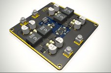
I think, i'm done for the first try.
4 phase boost with path-through, made for 600Wrms and 1200W peak, while peak-power is actually only limited by thermal design and input voltage. In theory, this setup should do 4x20A = 80A cont. from a single 12V SLA battery, giving some 960W*0.94 (900W) at the output. Increasing the input voltage will output more power.
PCB size is 100x100mm, as usual.

Using only 2 of possible 4 phases resulted in these values in simulation:
Loop-params:
Vin=20V und Iout=1A: BW 22.4kHz, 69° PM
Vin=20V und Iout=10A: BW 22.4kHz, 59° PM
Vin=20V und Iout=30A: BW 25.1kHz, 36° PM
Vin=27V und Iout=1A: BW 28.2kHz, 68° PM
Vin=27V und Iout=10A: BW 28.2kHz, 61° PM
Vin=27V und Iout=30A: BW 31.6kHz, 43° PM
Vin=31V und Iout=1A: BW 31.6kHz, 66° PM
Vin=31V und Iout=10A: BW 31.6kHz, 60° PM
Vin=31V und Iout=30A: BW 35.5kHz, 44° PM
Having 20+kHz loop bandwidth, i'd call this a fast supply.
I think, i'm done for the first try.
4 phase boost with path-through, made for 600Wrms and 1200W peak, while peak-power is actually only limited by thermal design and input voltage. In theory, this setup should do 4x20A = 80A cont. from a single 12V SLA battery, giving some 960W*0.94 (900W) at the output. Increasing the input voltage will output more power.
PCB size is 100x100mm, as usual.
Using only 2 of possible 4 phases resulted in these values in simulation:
Loop-params:
Vin=20V und Iout=1A: BW 22.4kHz, 69° PM
Vin=20V und Iout=10A: BW 22.4kHz, 59° PM
Vin=20V und Iout=30A: BW 25.1kHz, 36° PM
Vin=27V und Iout=1A: BW 28.2kHz, 68° PM
Vin=27V und Iout=10A: BW 28.2kHz, 61° PM
Vin=27V und Iout=30A: BW 31.6kHz, 43° PM
Vin=31V und Iout=1A: BW 31.6kHz, 66° PM
Vin=31V und Iout=10A: BW 31.6kHz, 60° PM
Vin=31V und Iout=30A: BW 35.5kHz, 44° PM
Having 20+kHz loop bandwidth, i'd call this a fast supply.
Attachments
Well, the "el cheapo" TL494 based boost-converters are limited to 20/30A at best, so using them with only 12V input voltage wont give the "extra punch" +3dB in bass we can get from a 4 phase converter with much higher bandwidth. 😀
SURE/Wondom is offerinh a TL494 based solution in similar size but with a big heatsink - rated at 500W output power running at 55kHz.
The Teufel Rockster "Boombox" btw. is also using a 4 phase converter, limited to 400W.
SURE/Wondom is offerinh a TL494 based solution in similar size but with a big heatsink - rated at 500W output power running at 55kHz.
The Teufel Rockster "Boombox" btw. is also using a 4 phase converter, limited to 400W.
Last edited:
I was looking at the different, more "finished" solutions. The design on the following seems reasonable, possibly without the many issues the more reference styled designs have:
Yuan Jing Audio - TPA3255 Class-D 2.1 Stereo Amplifier [150W x 2] + Sub-Woofer [325W] + Audio Tuning + Bluetooth - USD $95.50 - Multi-Channels Features
This is an updated version of the YJHIFI design with an older bluetooth chip. Any thoughts? But what I'm really wondering is ... why are there so many 2.1 TPA3255 amps from China with no LF-crossover frequency adjustment? The size of a
passive subwoofer choke would be massive, so surely these aren't designed with a choke in mind?
Pretty sure you can still get the TI 3255 EVM for $75, which, all in all, is the most polished ready-to-go board. Very very little work to get it configured for 2.1.
[I've not seen anybody put a value on it's sound, or place it in any league with recognisable competition. Except besides the 3116. It that's the closest measure, perhaps we know enough.
I have many amplifiers, 30 or more, and the TPA3255 is in another league from the 3116. Most of the amplifiers I have built are class A SS and tubes. Firstwatt clones and tube amplifiers such as SE300B, SE45 and a couple of SE-El34. The 3255 is an amp I could live with and not miss anything. I do prefer some of my other amplifiers over it but only by a small measure.[/QUOTE]Wdecho, could you compare the 3255 with a Jean Hiraga Class A? How would you rate the op of 3255?
- Home
- Amplifiers
- Class D
- TPA3255 - all about DIY, Discussion, Design etc