well, i would say that designing own DAC board from scratch makes more sense if the goal is to implement the best practices and components. otherwise we can just correct the most obvious glitches in a cheep ebay board ...
Interesting find. I should request a data sheet. Probably have to buy $150 worth for one of the distributors to provide samples. That seems to be the minimum order for anything, $150, plus shipping & handling, tax, whatever else. Of course, probably end up with several of them in the order.
ES9311 is used in S2 box, if I remember correctly. no magic bullet afterall
Designing a DAC board from scratch could be an interesting project. We have learned a lot from this exercise and I think we could do it. Could write firmware too.
However, I would like to see more people mod and report back.
I would like to finish working on my opamp heating thing, and
I would like to settle a little more on power supply architecture.
However, a basic, low-cost, sound-quality-first, selectable on-board upconversion, power supply design included, (optional?) HPA output, would all be features I would want to see. I think they are all required to meet the sound quality first goal. Maybe a place to put an Amanero USB board.
Maybe just a PCB and a BOM, or maybe with soldered SMD parts, maybe assembled, maybe assembled with a case??? I'm retired, not up for going into business myself. Maybe somebody would like to do a TP type of thing?
Regarding the 'otherwise' part, fixing the most obvious problems with the ebay DAC, I'm very near done. Heat and PS are all I have left on my list.
However, I don't expect people to build tiny circuits like I did, it was an experiment on my part to see if I could do it and to try to reduce the chances I would have to track down problems from using long wire runs. Turns out I have to track down a heating problem that may be due to my choice of layout. If so, it didn't work out as well as I might have hoped. Just have to fix it though. I'm working on it.
The very annoying habit of lumping feedback of similar, but different product together is NOT an ebay exclusive. Amazon is a much bigger offender in this regard. It would be helpful if the feedback author include the seller's shop name in their write-up.If you noticed every single board by every seller that is listed under the description: "ES9038 Q2M DAC DSD Decoder Support IIS DSD 384KHz Coaxial Fiber DOP"
all of them have been given the exact same reviews by ebay! In case you don't know about it, ebay suggests to the seller what description to use. So it is actually ebay that is primarily responsible for the review being attached to so many items, some of which sell for lower cost by the way.
Whoever the buyer was it sounds like that buyer and all the other buyers found they had to modify the board to give improved sound sound quality. In fact, it looks like that buyer was the least satisfied of all the buyers who commented. I would agree with the review that my particular board was well constructed in the sense of being well soldered, parts aligned well with solder pads, clean, board is thick and sturdy enough to have some strength, holes are provided for mounting, etc. I would also agree that the particular seller I purchased from answered one question I had promptly which I thought was considerate (don't remember who it was but they were in China and didn't really speak much English), but it couldn't have been the seller in most of those ads since they are all different sellers, at least so far as I can tell.
You can thank ebay for putting the same comments with many different sellers and perhaps products. Next time you might want bear that dubious practice of ebay in mind. Also, I see that ebay didn't put any of the words in the review in bold lettering, so it seems to read a little differently sitting there with the other reviews.
Anyway, please let us know when you get the board. We are looking forward to your upgrade reports and listening impressions.
The bold letter in the quoted feedback was what caught my eyes, not in the original. The board offered by different seller are all stamped SMPCS. There are RV1.02 which has a different layout than RV1.06 and RV1.07. The later has a jack for single polarity power input and connector for TFT display. I purchased an assembled box without the power supply.
ES9038 ES9038Q2M DAC Decoder board Support IIS DSD DOP 384KHz with Amanero USB | eBay
I already have a plan for the LDO linear power supply using LT1083CP and a small toroidal transformer. I will try both the unbalanced and balanced (+/-15v) one. I am still figuring out how to best implement the I/V output.
Last edited:
my mods so far
Hello,
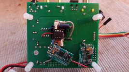
I would like to let you know my current mods and what I am going to do next. Pls. see my pictures below. The board still runs in voltage mode, but the improvements were already audible:
1) AVCC with opamp PSU according to ess recommendation with its own reg board providing 3,3V ref. fed from a sigma 11 PSU 5V - the clearest improvement in SQ so far.
2) seperate reg for clock from same external 5V sigma11 PSU - gives some finer structure in heights - maybe just psychological fulfilled expectation
3) substitution of onboard 8V reg fed by external 5V sigma 11 PSU (same as 1) and 2).
Next step is current mode output stage. I reviewed the es9028q2m board with i/v stage (see my post #594) and saw, that the differential circuit part is the same as on the stock es9038q2m board - just have to change one resistor 3k3 -> 6k2. As the sound of this es 9028 board and also measurements done here are not bad, I will just do the i/v conversion on a perforated test board on bottom side with TH components. I would use the same values for inverting feedback circuit as on my es9028 board, which are 330 Ohm//100pF and seem to work quite well - at least with es9028. Is there a reason why Mark and Victor choose 820 Ohm // 220pF?
Hello,
I would like to let you know my current mods and what I am going to do next. Pls. see my pictures below. The board still runs in voltage mode, but the improvements were already audible:
1) AVCC with opamp PSU according to ess recommendation with its own reg board providing 3,3V ref. fed from a sigma 11 PSU 5V - the clearest improvement in SQ so far.
2) seperate reg for clock from same external 5V sigma11 PSU - gives some finer structure in heights - maybe just psychological fulfilled expectation
3) substitution of onboard 8V reg fed by external 5V sigma 11 PSU (same as 1) and 2).
Next step is current mode output stage. I reviewed the es9028q2m board with i/v stage (see my post #594) and saw, that the differential circuit part is the same as on the stock es9038q2m board - just have to change one resistor 3k3 -> 6k2. As the sound of this es 9028 board and also measurements done here are not bad, I will just do the i/v conversion on a perforated test board on bottom side with TH components. I would use the same values for inverting feedback circuit as on my es9028 board, which are 330 Ohm//100pF and seem to work quite well - at least with es9028. Is there a reason why Mark and Victor choose 820 Ohm // 220pF?
Attachments

Last edited:
The stock differential output has an adjustable DC offset. If the solder jumper is set to run on a single + rail supply, then the DC offset is 1/2 of the + rail, otherwise instead of that node is suspended about half way between the + and - rails using a voltage divider. There are caps to more or less ground the node for AC. When people sketch out the stock output stage for some reason they never trace out far enough to see how that works, or if they do they leave it out of the drawing. That probably not desirable if going for more more a high performance low distortion output. Probably best to remove that stuff and make sure the node is also grounded at DC.
In addition to help cancel out distortion by combining the inverting and non-inverting DAC output differential, it is important that the gains are accurate so that maximum cancellation occurs, and maximum CMRR is achieved. Unfortunately, we don't know anything about the parts used on the stock circuit except that they are probably cheap.
It is important that all caps in the signal path and filtering be COG and that the resistors are all thin film and high precision. I used .01% tolerance where I could such as in the differential stage, and .1% for the IV stages. Maybe possible to do a little better as there are also some resistors available in .05% tolerance.
So if the goal is to get the the best sound quality while reusing as much as possible, I would use the top part of the board but replace the SMD components with good ones, and make sure they are known to meet ESS recommendations or better.
.
2) seperate reg for clock from same external 5V sigma11 PSU - gives some finer structure in heights - maybe just psychological fulfilled expectation
That was about my impression when I put the clock on its own regulator, although it was already modded with a Crystek clock. It did seem to help the highs but in a subtle way. I don't know if that would be because of clock improvement or due to getting some clock noise off of the 3.3v bus. Since we both seem to have heard it about the same way, I am inclined to think something real is most likely going on.
is that an AudioFeel discrete op amp you have on the second pic?
yes, it is. I could not hear an improvement on this board against a LME49720. On my AK4495 board the improvement was much more audible with this descrete op-amp
Mark,
Thanks for the hint with the caps! I have to check the circuit again - I thought the 2 small caps close to the jumpers are grounded on both sides when jumpers are set to dual voltage, so no impact. If so, the circuit is as my 9028 (except the 3k3 resistor). should I better remove them though?
As written before, it is nearly impossible for me to find COG caps in desired values and 1206 size and small qty. - same for thin film resistors. That is one reason why I would like to keep the circuit as it is and just set it into current mode. Probably I find smt metal film resistors with 1% tolerance and solder TH film caps to the smt solder points in a further improvement step, to substitute the stock components on board?
Mark, straight saw, there was a design change in the node you mentioned above from my V1.04 to V1.06 you have. Nevertheless I should remove some trace here and also the caps, to get the same circuit as on my es9028 board.
As you said before, it helps to talk about the things before doing it..;-)
As you said before, it helps to talk about the things before doing it..;-)
yes, it is. I could not hear an improvement on this board against a LME49720. On my AK4495 board the improvement was much more audible with this descrete op-amp
it runs in class A and ads some nice sounding harmonics. may get pretty hot though.
Mark,
As written before, it is nearly impossible for me to find COG caps in desired values and 1206 size and small qty. - same for thin film resistors.
The 1/8 watt SMD thin film resistors aren't hard to solder, IMHO. The usual trick of putting a little blob of solder on one pad works, the holding the part in tweezers and pushing one end into the melted solder blob. Let the board cool, then solder the other side. If the part wont reach, solder a small piece of stripped wire wrap wire onto the other pad so that one end touches the unsoldered end of the part. Let it cool. The quickly solder the end of the wire wrap wire to the part. If that might melt the wire wrap wire on the solder pad, then leave other end of the wire long and tape it down before soldering to the pad. Don't remove the tape until both ends are soldered. Then remove the tape and clip off the extra wire wrap wire.
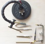
There is a very good way to hold down little SMD parts that I use, but I have not seen anyone else use. I use a device I made the has various attachments for soldering. Please see pics below. There are two SMD soldering holders with spring loaded tips. One has a single point and other has sort of a double pointed saddle shape which is for small round diodes. They are made from automatic center punches with the trigger/hammer mechanisms removed but with the spring loaded plunger retained.
I use the other attachments like with the alligator clips all the time to hold wires.
What I do with SMD parts is clamp the PCB by the edges in a machinist vise, then use the pointy plunger to hold the SMD in place to solder the first side. After letting it cool a little the other side is safe to solder without holding down if using a low temperature solder an iron.
Also, because SMD parts can be quite small it is necessary to align the pointy tip carefully over the center of the part. Sometimes it is easier to slide the PCB and vice around slightly rather than move the holder.
The arm that the solder gizmo uses is a dial indicator holder so it is precise. It also as a little knob at the base to tip it on one axis. That can be used to gently lower the point onto the SMD part. With a little practice on junk parts or one of those little SMD soldering practice kits it works quite well. I'm no longer intimidated by small parts.
One thing I found out along the way that gave me some frustration was having small parts pop out of my tweezers. After looking into the problem I discovered the tweezers weren't all that well made but there are none better available. I just filed down the tips to a perfectly matched alignment. Also if using curved tweezers need to file the inner surface of the curve because if squeezing curved tweezers tight they actually open at the end. As pressure is increase first they close, then tighten, then start to open at the end. It turns out flexing in the tweezer arms and the inside surfaces at the curve touching acts as a fulcrum to make the end open. Filing off the material from where they touch fixes that.
So, in sort, it is a matter of practice and using the right tools, some of which you need to mod or make yourself. But once you are set up you can do almost anything. I was really surprised to find what I could do. Never expected it was possible for me.
I would be happy to post more detailed pictures of the SMD procedure if anyone is interesting in seeing how to do it.
Attachments

Last edited:
Thank you Mark, for this good advises - it might courage me to try it with the 0806 smt size resistors...
I also found a good helper in a sticky rubber gum used for tightening car body sheets. It can hold down wires and other small components without having to (fine) adjust clamps on a mechanical structure. Might also hold down a fine clamp that holds a smt resistor - never tried this, but it is a very good helper and dont want to miss it anymore.
I also found a good helper in a sticky rubber gum used for tightening car body sheets. It can hold down wires and other small components without having to (fine) adjust clamps on a mechanical structure. Might also hold down a fine clamp that holds a smt resistor - never tried this, but it is a very good helper and dont want to miss it anymore.
it runs in class A and ads some nice sounding harmonics. may get pretty hot though.
I heard that it can get hot, but I think it depends on feedback resistor value. There are different types of this board, pending of the feedback resistor. Mine never became hot and I like the feature to adjust DC-offset on the output.
Did you measure harmonics of such opamp board?
Was just looking at LT3045 datasheet. Interesting. It sounds like to get full performance it needs attention to all the little details similar the DAC chip itself. In particular, it seems that LT3045 and LT3042 are especially sensitive to stray magnet coupling. That, and because to get down to -120dB level performance all the little details matter even if it is a voltage regulator instead of a DAC.
If the module designers did the same quality job with the regulator modules as with Chinese DAC boards, maybe no wonder people haven't seen sound quality perhaps as good as anticipated and perhaps as good as the ESS op amp circuit. Don't know of course, but for it to be a fair comparison one might need to read the LT3045 application notes carefully and also read the "DEMO MANUAL DC2491A" demo board manual, which is recommended to read in the LT3045 application notes.
There is also the application note an159fa.pdf, entitled "Measuring 2nV/√Hz Noise and 120dB Supply Rejection on Linear Regulators," that may be informative.
So, before I go off and do a lot of reading, has anybody else studied the documentation carefully and followed all the recommendations to get full -120dB rated LT3045 performance? If it has been tested carefully for AVCC supply use with attention to small details and DAC sound quality is not good enough then no need for me to repeat the experiment.
I pointed out in a prior post about the load transient response about these 3042/3045 before. First for the rated output current of each device, the overshoot in output voltage is 20mV. So for the 3045 rated at 500mA and 3042 rated at 200mA. They both overshoot when the load is a pulse. Now what is interesting is that they BOTH overshoot the same amount despite one rated at 2.5X the output of the other one. That leads me to believe that even with lower currents, the overshoot in voltage output will be equally high....at 20mV. That is not acceptable for AVCC. You need 1 uV for each decibel down there. So these devices might be suitable for steady current output not dynamic loads.
Even the LT1963 display this characteristic as well and it is rated at 1.5A.
Even if the overshoot decreased with smaller current loads, then the LT1963 might be better for the proportionality aspect.
Are all monolithic regs this poor in voltage output when subjected to pulsed loads...which is what i think DAC AVCC creates.
Might the op amp respond better when subjected to transient loading?
I am not trained as an EE but ME and most of my career has been on the business end not technical. So I could easily be totally wrong here.
Last edited:
I am thinking of using video op amps for AVCC now. Anyone see a reason why these would not be suitable?
I am waiting for a DAC to resume my experiments.
I am waiting for a DAC to resume my experiments.
20mv pulse noise is measured with 200ma loads for lt3024 and 500ma for lt3045 and are not even close similar... At 200ma will 3045 have far les pulse noise.
Es9038q2m is power easy version so it us about 5ma on each pin what is easy job for both of them. So i am excited what will be opamp Avcc regulator bringing.
Es9038q2m is power easy version so it us about 5ma on each pin what is easy job for both of them. So i am excited what will be opamp Avcc regulator bringing.
Food for thought? Check out post #318
ES9018K2M, ES9028Q2M, 9038Q2M DSD/I2S DAC HATs for Raspberry Pi
ES9018K2M, ES9028Q2M, 9038Q2M DSD/I2S DAC HATs for Raspberry Pi
- Home
- Source & Line
- Digital Line Level
- ES9038Q2M Board