Thanks, Mark! the last iteration conceptionally seems to be similar to yours minus oscillator improvement and I am using I2S (the DAC will get the stream from RPI3). of course TH instead of SMD, different op amps and at the moment all this is just a quick prototype to see how the things work. anyway I can not measure more than about -100dB, so that perhaps is the limit for this case and I am not aiming to match a real HIFI leaving this for 2 other projects in parallel: es9028pro and AK4497.
to me the biggest difference appears how we get appropriate AVCC. yours use an integral LDO reg and an op amp buffer according to ESS design. I trust in simple series regs. they have low impedance over wide frequency range and importantly are good for loads with quickly changing current draw. I believe this technical diversity might be for common benefit.
So the current separate AVCC supply is fine for me in this case. for other consumers an integral reg(s) should be good enough. have to decide still which I/V version to use and what about the oscillator. next I have a temptation for a custom FIR filter. that would need an arduino hookup and finding out how to upload coefficients. at the moment I am not even sure that is possible on a mobile chip. but that most likely deserves another thread to discuss.
Eziitis, will you be starting a thread on the 9028pro?
unfortunately not at the moment. I will continue with AK4497 next and I think there was a pretty good thread already.
es9028pro board is not so bad in stock but has some bottlenecks. First off AVCC of course, next I/V. DAC puts out about 16mA and one may want to reduce FB resistor value, but then the opamp needs to be up to the task. this is 4 layer board and reworking has to be done carefully. topology is not so simple as here.
and yes, for this board the seller usually can provide a schematic.
Last edited:
It turns out it depends the quality of the upsampling software. Even SRC4392 is slightly audible, I think. About the same as Reaper using the Extreme High Quality mode, which is to say, around -140dB. Although the filtering in Reaper sounds a bit different than SRC4392. Only thing better is the software resampler called Saracon @ -160dB, by Weiss. But, at its price it is unobtainium for the masses. Virtually everything else is worse than those I mentioned. Maybe there is something I missed but there used to be a webpage somewhere with measurements of all the software resamplers. IIRC, Reaper Extreme Quality Mode was 2nd only to Saracon of those they measured and there were a lot of them, again, IIRC.
Anyway, if the 2nd best is audible at all measured at around -140dB, and also distinguishable from a hardware SRC resampler spec'ed at -140dB, presumably all the others are audible too and probably less good. In addition, maybe there is something else going on that distinguishes them besides what is measured, I don't know, and I don't know why I hear a difference. To me Reaper is more smeared and SRC4392 is more grainy, but its very, very small. Most people will never notice, I tried asking a few and they didn't. Small sample though.
EDIT: What is measured is probably nonlinear distortion, and what I hear is presumably linear distortion at a more audible level. That would probably make more sense. Bottom line though, I would think if you can hear differences between resamplers then pick one you like. I like SRC4392 pretty well, definitely I like the DAC better with the SRC than without it.
Last edited:
ok, thanks, need to think over different options then. one thing is I have quite a few my old vinyls put in a "dustpoof" DSD128 envelopes. at the moment they go iFi/S2 native DSD way. not so clear whether SRC board and SPDIF then will be any good.
If sample rate is already high enough it seems doubtful there would be benefit, or as much benefit, but haven't tried to test that speculation. Only say 'as much benefit' because some mix engineers I respect claim to hear differences. I know there are some people who are much more skilled and able listeners than I am, I just don't know how many. No idea.
Last edited:
http://waltjung.org/PDFs/ADI_2002_Seminar_Ch6_Audio_Drivers_I.pdf
Finally found it!
Check out page 9
Also on Page 15, there is something that could be considered. That is distortion increases generally in these low current op amps as current output requirements rises. It indicates that paralleled opamps gives less distortion than using a single one when it is driven hard. Hmm.... ideas for the AVCC regulator here ? I knew I saw this somewhere and that is about 24 years ago!
Also a nice discussion of the AD797 that Eziitis has shown to work well and ESS recommends it as well for a reason. Page 16. Some thoughts for possibly more improvement.
It depends what hard is for a given op amp. For audio specific ones like 5532 and 49720, they can drive 600 ohm loads without a problem. Not for TL072, it distorts more unless at least around 2k load. That no doubt is one part of the reason ESS strongly recommended the op amps they did. And sure, AD797 may be a better choice for AVCC than 49720, at least if ES9038Q2M uses more current than the old ESS application note, probably for ES9018, shows. However, for normal use by ESS standards Q2M might need 6mA, however I don't know if our use is more or less 'ESS standard' or not and if not then how different is it. It may well be more but probably not more than 49720 can handle for AVCC. The PRO chips are a different matter. They aren't intended to be able to run off cell phone batteries.
As far as for IV stages, the load resistor is 820 ohms and the op amp output is only swinging around, what was it, 1v p_p? That is not a heavy load for 49720.
It still would be a good idea for someone to measure AVCC current draw, including for the highest possible sample rates, and including for DoP and DSD. That would be useful information. Speculation is not really much help though. Unfortunately, I only have sources up to 192kHz, and no DSD or DoP (shows how old fashioned I am I guess).
Last edited:
Hello Mark,
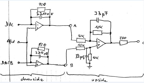
I tried to figure out your circuit for output stage from your pictures. Is it correct like below? What cap values did you choose? Could I use film caps here as well?
It looks more simple than the ess recommanded circuit - there are no filter caps on upper side (sum-opamp circuit) and also no caps between the outputs of i/v converter stage - any reason for it?
Attachments

Hello Mark,
I tried to figure out your circuit for output stage from your pictures. Is it correct like below? What cap values did you choose?
Yes. The IV stage caps are 220pf, COG dielectric.
More recently I added two 33pf COG caps to each the differential amp stages. The is one cap from the non-inverting input to ground, and one from the inverting input to the output. Standard locations to roll off a differential amp.
In addition, I should probably mention that I have noticed my opamps getting warmer than seems reasonable. I suspect but don't know they may be getting some RF into them, maybe through the power supply. I am planning to run the digital circuits from a separate power supply as an experiment to see what that shows. Also, thinking about programming the Q2M to lower its clock speed with an internal divider to see if that has any effect.
In short, I think the basic circuits I used should work well and not run too hot. They are fairly similar to the corresponding ESS recommended circuit except that ESS does more HF filtering at the differential amp stage to reduce HF noise coming presumably from the DAC outputs. They don't do the extra filtering for their differential analog outputs though, which makes me think it may not be essential. That being said I would probably recommend their circuit over mine with respect to the additional filtering. It's not a bad idea, I just didn't do it because I had precision 10k resistors in stock and not the other ESS recommended parts.
I expect I will probably figure out whatever is going on with op amp temps fairly soon, but for now the project remains a work in progress. It may be by the time I get to power supply recommendations I will include some other new considerations that I don't know about yet.
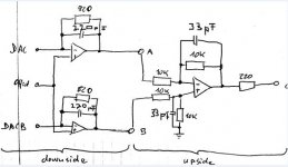
Correct. There is power supply decoupling also, of course. You do have it correct for the DAC output signal flow.
eziitis, I found another seller, Dougmall, of the same PSU, at higher price. The item description has more details, but somewhat confusing. Still no spec on the noise level.I would recommend this one PS ... HIFI DAC Power Board Fever DAC Power Supply Board +- 12V 5V replace LT1963AEQ | eBay
it has also +5V
The module uses high-speed op amp + high-current MOS transistor pure A parallel structure, the output current is large, the ripple is low, ultra-low internal resistance, the voltage is affected by the load, suitable for power supply of low-power amplifier / preamp / DAC decoding and other equipment .
Features
1.5A output current
Input voltage 5V-30V
High-current Schottky diode rectifier
Full precision wafer resistance
Each Channel 6800UF high capacity capacitor
Ultra low internal resistance
Output voltage: ± 12V, 5V
Output circuit: 1.5A max
Size: W97.5 × L96 × H40 mm
I usually take their spec with a grain of salt. It is best to test it yourself.
This is a good transformer match for this PSU, with 4 separate windings.
115V/230V 30W High Quality Audio R-Core Transformer 15V+15V 9V+9V For Preamp 699939635317 | eBay
Last edited:
I hope that some ebay seller will catch on and make a kit for it.Hello Mark,
I see. so below is your current set-up - correct?
Even if somebody did make an ebay kit they would probably cut corners on component quality. Use worse tolerance caps and resistors, only use one electrolytic decoupling cap per rail and no ceramics at the chips, etc. That just seems to be how they do it. Then you would have to mod it, etc.
Otherwise, why doesn't someone just make a basic DAC that puts sound quality before bells and whistles? I think the answer would be because that isn't what most people shop for on ebay. They want a good looking box (or a board with components with visual appearance similar to name brand parts) and a few words suggesting the brand name of the chip inside is enough to know if the sound quality will be really good.
Having a small but not excessive number of options for customization seems to help sell too, at least that is what research shows (see: Cialdini). One op amp in a socket is great for that. Customizable, but not to excessively complicated to understand and do.
These are used as texts in business schools to teach selling:
Influence: The Psychology of Persuasion, Revised Edition: Robert B. Cialdini: 8580001041766: Amazon.com: Books
Pre-Suasion: A Revolutionary Way to Influence and Persuade: Robert Cialdini Ph.D.: 0884356092472: Amazon.com: Books
Last edited:
@keilau, I have not measured the noise, but if everything else is fine then it mostly will depend on voltage reference, tl431 in this case. should be more than enough for a pre-regulator.
What one needs is someone here who can design and get the board made. It is not likely to happen on Ebay as that is a VERY competitive market. There are some gems by chance once in a while.
This mod is a very limited market and in reality possibly not enough to generate enough volume to justify the risk and expense that someone would need to take to serve that need especially with SMD. The best I think that can be done is if someone makes a through hole board that would take care of this and generate a group buy.
I had been looking at prefabbed boards that might be able to be redeployed and I have found a couple that might be able to serve as AVCC. For the IV section, I found none.
I purchased this DAC with no initial intention to take it this far but I am glad that I did, till I killed the board. But having learnt from this I think any mod that attempts to take it this this far as to potential sound quality is possibly better done with an initial board that already encompasses the 3 op amp architecture. The less expensive DACs that use one op amp simply requires too much modding to correct it.
This thought was somewhat confirmed by exiitis with his finding of using the AD797 to reduce the second harmonic was needed.
So my opinion is that this board in practical terms can be modded to fix AVCC with a dual op amp reg and possibly a crystal change and the usual op amp rolling. Taking it beyond that is probably a limted prospect for the person that this DAC was initially aimed at.
I just wished that there was a 9028pro project that would take this to this level and beyond as I think that the diyer purchasing that DAC would be more interested in the upper echelons of modding the DAC.
Markw4. Any prospects of doing this?
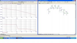
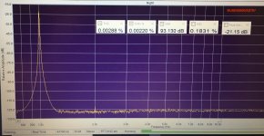
actually, this is an OT and I have not done much with 9028pro board, but maybe you can judge from the info attached. it is pretty obvious it may need some mods starting from AVCC, other power sources and I/V.
note, that component values in the schematic are not correct for the particular board, since the same PCB has been used for 9018, 9028 and even for 9038 DACs 😱
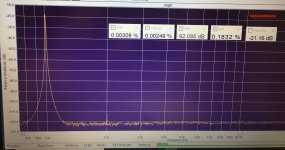
still in stock it measures about -92dB vs -76dB stock for the board discussed here. perhaps not so bad for the money paid ... those fancy op amps give some reduction in the 2nd harmonic, so not entirely worthless.
note, that component values in the schematic are not correct for the particular board, since the same PCB has been used for 9018, 9028 and even for 9038 DACs 😱
still in stock it measures about -92dB vs -76dB stock for the board discussed here. perhaps not so bad for the money paid ... those fancy op amps give some reduction in the 2nd harmonic, so not entirely worthless.
Attachments
Last edited:
actually, this is an OT and I have not done much with 9028pro board, but maybe you can judge from the info attached. it is pretty obvious it may need some mods starting from AVCC, other power sources and I/V.
note, that component values in the schematic are not correct for the particular board, since the same PCB has been used for 9018, 9028 and even for 9038 DACs 😱
still in stock it measures about -92dB vs -76dB stock for the board discussed here. perhaps not so bad for the money paid ... those fancy op amps give some reduction in the 2nd harmonic, so not entirely worthless.
Hello
What do you suggest for :it is pretty obvious it may need some mods starting from AVCC
Thanks
Serge
I wonder if the es9028q2m board shown from eziitis in post 1133 (and from me earlier before) is not a better starting base for all who are OK with an I2S input. The board is available with and without master clock on board and it comes with the i/v stage already on board incl. PSU. The only mod needed would be AVCC (and clock PSU). Does anybody know which are the according pins for es9028q2m here? Does the 9038 sound that much better and is a missing filter setting possibility a problem?
One could also buy this board and cut the digital part away to combine it with the here discussed es9038q2m board. That way you have i/v stage + PSU all together and you can use the 3,3V PSU for digital section of the 9038 board.
My problem in building the board of Markw4 and modifying existing board is the availabillity of 1206 size smt components for thin film resistors and COG MLCC caps. So my question would be if also film caps and metall film resistors might do the job?
- Home
- Source & Line
- Digital Line Level
- ES9038Q2M Board