As you should see in my post above, I replaced the 270 k pulll up resistor with something else to make the voltage at the emitter of the input transistor idle about 1/2 the rail voltage. This minimizes 2nd harmonic distortion on large signals if the operating point stays near there.Just having had a close look at the circiutry in #1 again: Shouldn't the voltage divider provide a potential of about half the supply voltage for the first transistor's base?
Best regards!
As I had a very high gain input transistor and needed compatibility with a high impedance PAS2 tube preamp, I also increased the pulldown resistor to achieve about 500k input impedance.
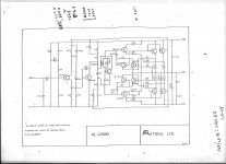
Here is the R.A. Penfold mosfet amp circuit for single supply up to 100v. I have built it and it works. It's similar to the MJR mosfet amp discussed elsewhere on the forum
Hi Bruce,
Which do you prefer in terms of sound quality of this R.A. Penfold mosfet amp vs AUTONA AL125?
Regards,
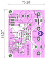
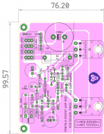
PCB for # 278 . Done quickly, please point errors or ask me to do something differently.
thimios, is this what you are looking for🙂?
Hope this isnt too divergent from Mr. Mile's subject thread😱.
otherwise, request mods to delete the post.
regards
Prasi
thimios, is this what you are looking for🙂?
Hope this isnt too divergent from Mr. Mile's subject thread😱.
otherwise, request mods to delete the post.
regards
Prasi
Attachments
Last edited:
IHMO The AL125 sounded much better. Maybe a member who has some spare time could do a board layout of the AL125 using MJL21194 flatpacks and pushing the rails to 100v which should give you app 100w into 8 and about 150 into 4 ohm. Th double bootstrap on the AL125 is also unique not something I have not seen a lot of. I did try bridging the modules with 2x AL125 with 2n3773 at 80v and doing away with the speaker bypass caps it worked perfectly for a while but one of the modules would start drifting so the midpoint voltage would have to be re adjusted.
IHMO The AL125 sounded much better. Maybe a member who has some spare time could do a board layout of the AL125 using MJL21194 flatpacks and pushing the rails to 100v which should give you app 100w into 8 and about 150 into 4 ohm. Th double bootstrap on the AL125 is also unique not something I have not seen a lot of. I did try bridging the modules with 2x AL125 with 2n3773 at 80v and doing away with the speaker bypass caps it worked perfectly for a while but one of the modules would start drifting so the midpoint voltage would have to be re adjusted.
Thank you Bruce for your inputs. Much appreciated.
PCB for # 278 . Done quickly, please point errors or ask me to do something differently.
thimios, is this what you are looking for🙂?
Hope this isnt too divergent from Mr. Mile's subject thread😱.
otherwise, request mods to delete the post.
regards
Prasi
Can someone tell, if this amp will work with modern more easily available devices? Just an exercise towards curiosity!😀.
regards
Prasi
Attachments
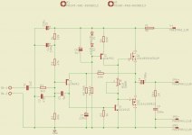
Hi Prasi,i mean this amplifier.😉
First we need someone to simulate this using now available parts.
First we need someone to simulate this using now available parts.
Attachments
Last edited:
Hi Prasi, like I said I did build the circuit and it did work although I did double up on the fets. I should imagine it would work just as well, if not better with the BUZ series fets or perhaps with a few modifications IRFP240/9240. Personally I did prefer the AL125 it seemed to have more bottom end. It would be great if someone could simulate it in LT spice ( something I am not too familiar with ). I have since found the original article for the AL125 module in the October 1980 copy of Pratical Electronics. As soon as I can scan and post it
Hi Prasi, like I said I did build the circuit
Did you use the B716/D756?
I am going ahead with placing an order for 20 boards as per post # 273 . they will be locally made single sided 1.6mm thk with green mask but with 70um Cu. So needs jumper.
1. Prasi 2 nos
2. Member (nareshn) thro PM 2 nos.
3. Bix 2 nos.
4. Indianajo 2 nos.
1. Prasi 2 nos
2. Member (nareshn) thro PM 2 nos.
3. Bix 2 nos.
4. Indianajo 2 nos.
Hi Prasi,i mean this amplifier.😉
First we need someone to simulate this using now available parts.
ok, lets wait!
ok, lets wait!
Yes my friend, let's wait someone to help with the simulation, then i know a good friend ho can do the rest.

P.S. the 'list'
1. Prasi 2 nos
2. Member thro PM 2 nos.
3. Indianajo 2 nos.
Hi Prasi
Just wondering roughly what sort of price point for a pair of PCB?
Cheers
Hi Prasi
Just wondering roughly what sort of price point for a pair of PCB?
Cheers
hello avtech,
8 usd base price for a pair of pcbs+shipping + paypal. So grand total of ~15 usd delivered via registered mail.
regards
Prasi
8 usd base price for a pair of pcbs+shipping + paypal. So grand total of ~15 usd delivered via registered mail.
😀 Sounds good.
Add me to your list please!
Yes my friend, let's wait someone to help with the simulation, then i know a good friend ho can do the rest.
😀, but I must say, its a bit confusing schematic with + and - shown as expressed by anti and also i/p and o/p ground connection not shown.
Last edited:
1. Prasi 2 nos
2. Member (nareshn) thro PM 2 nos.
3. Bix 2 nos.
4. Indianajo 2 nos.
5. avtech23 2 nos.
2. Member (nareshn) thro PM 2 nos.
3. Bix 2 nos.
4. Indianajo 2 nos.
5. avtech23 2 nos.
😀, but I must say, its a bit confusing schematic with + and - shown as expressed by anti.
Prasi,do not take the effort of a pcb making before someone can post a clear schematic and make sure that is a working amplifier in simulation at least.😱
"-" is the "power ground". So connect the "-" to the VAS ground and all will be clear fast. Add a 4700uF -or so- output cap and you're good to go. The schem posted here is imho a more "true" one - an opinion based solely on my eyeballing expertise.
Google finds this: Archives: Vintage Audio – The Autona 125 module – Online Parts International
And this: Autona AL125 - Analog Ian
So if you're really into vintage ... imho a good idea would be to cobble up a derated 80W or so version with 4x TIP3055 and a BD139-16 instead of the BC441.
IF you are adamant to follow the autona circuit ...
- Home
- Amplifiers
- Solid State
- Retro Amp 50W Single Supply