My questions were related to the nature of tube sound, not any specific design.
I've seen countless threads on this subject. They tend to go nowhere, and generally become an argue fest.
You've taken over a thread where people genuinely want to build this line stage, and enjoy it, instead of starting your own. Maybe it's time to move on.
jeff
There is no nature of tube sound. Each topology has own weak points that cause own type of distortions.
My questions had nothing to do with design, I was asking for a generalized subjective opinion about tube sound.
A few of us DID give you our opinions about tube sound. This didn't seem to go anywhere because you just disagreed and substituted your own opinions. The way to learn is to ask more questions and carefully consider the responses. Then ask more questions. It's iterative.
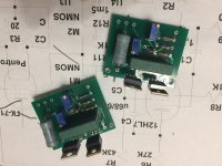
Guess who is getting some of Ale's Gyrator boards?????????????????????????
<-----------------Yup this guy right here 🙂
So yeah I am pretty stoked.
I haven't assembled Rod's regulator boards yet and I am still trying to figure out what I am going to use for a VAS. The VAS can be wimpy as I am going to use Pete's A2 Mosfet driver boards. I will go though my tubes and make a list, do some rough calculations and simulations, then move on to breadboarding. Off the top of my head I have lots of 6N3, 6SN7's, 6AU6A's, 5670's, and 12AX7's. I have some 5751's, 12AY7, 6072, and 12AT7'S. I have two Western Electric 396a's that I have been dying to try, if I go that route I think I can sub in 5670 and 6N3.
I am going to use for a VAS.
My rule of the thumb:
Going backward.
- Required swing;
- is A2 required?
- is CF or source follower required?
- VAS "R loaded", choke loeded or active loaded? This choice determinates B+ voltage;
- choose correct B+ voltage: if you use active load, B+ must be at least 50V greater than swing upper peak;
- use enough large anode current of moderate output impedance VAS device, or must be using low output impedance follower;The VAS can be wimpy
- anode swing, anode current and headroom define tube type;
Bias for 4P1L will be ~18-20v. And since I am going A2 then the grids need to go positive. By how much? I have no idea. I am guessing I want a gain of around 30.
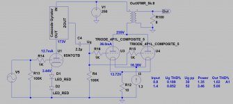
There will be a follower between the VAS and the 4P1L's.
The VAS will be actively loaded by a gyrator.
B+ is roughly 250. So if I set the VAS anode to 150 there should be plenty of headroom.
There will be a follower between the VAS and the 4P1L's.
The VAS will be actively loaded by a gyrator.
B+ is roughly 250. So if I set the VAS anode to 150 there should be plenty of headroom.
As you can see in datasheet even +12..16V is in the "working" area (with grooving distortion).And since I am going A2 then the grids need to go positive. By how much? I have no idea.
Attached an example:
15V peek grid voltage is the A1 border, 26V (deep in A2) is below clipping.
Attachments
Bias for 4P1L will be ~18-20v. And since I am going A2 then the grids need to go positive. By how much? I have no idea. I am guessing I want a gain of around 30.
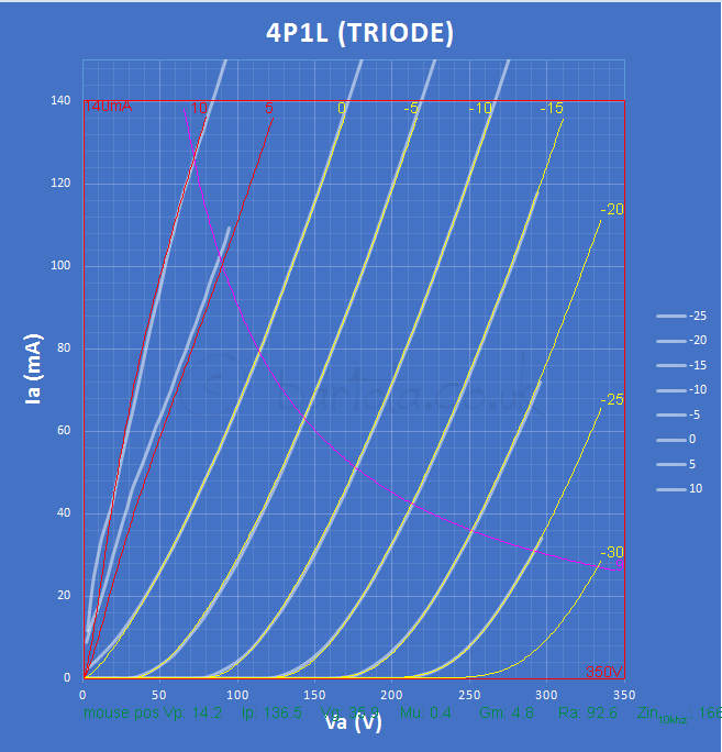
Here are the curves I traced with A2:
And here is the grid current:
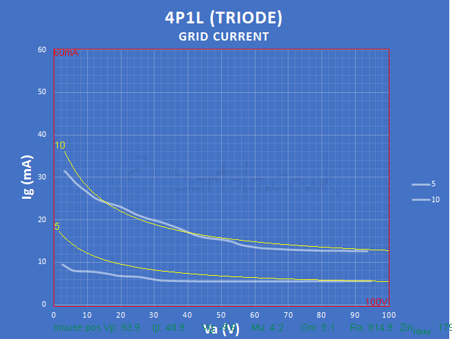
With a 3K2 loadline you wouldn't need higher than 20-25V. A source follower or cathode follower would be required to provide the grid current without distortion with DC coupling to the grid.
I posted earlier a design or you could look at Anatoliy's A2 design with cathode follower.
A simple SF with a bipolar 50V will do the job very well.
If I get the time I will retrace the 4P1L in A2 with the eTracer which is better fit for this job than the uTracer I believe.
The spice model is in my blog somewhere if you want to play with the circuit and simulate the response.
Cheers
Ale
Yes, -100V would be enough. My boards are similar to Pete's, except I have on them also anode load resistor for a driver stage, and a coupling cap. And 2 multutirn pots, one to set idle current, another one to set bias voltage.
Yes, -100V would be enough. My boards are similar to Pete's, except I have on them also anode load resistor for a driver stage, and a coupling cap. And 2 multutirn pots, one to set idle current, another one to set bias voltage.
I have a 40v, 4.4VA Hammond Transformer that should work. 100mA should be plenty i would think right?
I am trying to get all my parts together so when Ale's boards arrive I can start assembly. I want to be listening to 4P1L's ASAP.
So will 4.4VA be enough for my bias and negative rail?
I am trying to picture where the DC will flow with two rails. So I set the A2 board for 10mA each device for a total of 20mA. This 20mA current is flowing through both supplies correct? So from my large power transformer I can add 20mA to the total load and also add it to the negative supply transformer rail. This leaves me with 80mA left for grid current during transients and whatever small amount of current the bias resistors will carry. I am also trying to calculate ripple for my bias supply and need to know the currents for filtering. I think I will add a small choke for an LCRC bias supply, I want the grids to be dead quiet.
So I don't need to order a larger transformer for bias and negative rail?
Last edited:
I have a 40v, 4.4VA Hammond Transformer that should work. 100mA should be plenty i would think right?
More than plenty.
I built a balanced preamp using 01A. I used a Hammond 124B as a balanced plate choke - sounded nice. It's 49% nickel. But after that I went all SE, so no further interest.
Last edited:
- Home
- Amplifiers
- Tubes / Valves
- 4P1L DHT Line Stage