Please tell me!
I have a 220W transformer, with 40-0-40 ac output. Can I build AX-14 with a pair of NJW3281G / NJW1302G?
Sorry my english is not good.
I have a 220W transformer, with 40-0-40 ac output. Can I build AX-14 with a pair of NJW3281G / NJW1302G?
Sorry my english is not good.
No, that is not the correct way to measure bias. Bias is measured "across" emitter resistor. + or red Probe to emitter side of the resistor and - or black probe of DMM to "speaker out" side of the resistor..😉
dear, Prasi
please read #1599
To check DC out: Connect input GND to PSU GND and place your DMM test probes black to PSU GND and red or positive probe to Speaker out (reading should be in mV DC).
Bias setup: Place your DMM negative probe to Gnd. and Positive to R33/5W or Emitter of 2SC5200/2SA1943 and adjust 1K trimmer to 15mV DC.
Hope this will help…
No,this is nothing to do with bias adj.dear, Prasi
please read #1599
To check DC out: Connect input GND to PSU GND and place your DMM test probes black to PSU GND and red or positive probe to Speaker out (reading should be in mV DC).
Bias setup: Place your DMM negative probe to Gnd. and Positive to R33/5W or Emitter of 2SC5200/2SA1943 and adjust 1K trimmer to 15mV DC.
Hope this will help…
Look at the picture,you can see the bias setting voltmeter position.
Short amplifier's input.Connect the voltmeter as at the picture.Turn amplifier on,read the voltmeter,adjust according manufacturer guides.
You MUST do this AFTER the first power on ADJUSTMENT USING PROTECTIVE RESISTORS.
This procedure is common for all amplifiers bias adjustment.
Attachments
Last edited:
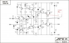
Look here,R8=1K instead of 560R for higher gain amplifier.Hello Thimios
Can you tell me exactly which component I have to cheng to increase AX-14 amp gain without changing its stability.Rail voltage is +/-46vdc is it an ok or bit low for required voltage.
Thanks for helping me.
Best regards
Attachments
Look here,R8=1K instead of 560R for higher gain amplifier.
No, use 330R instead 560R for higher gain.
No,this is nothing to do with bias adj.
Look at the picture,you can see the bias setting voltmeter position.
Short amplifier's input.Connect the voltmeter as at the picture.Turn amplifier on,read the voltmeter,adjust according manufacturer guides.
You MUST do this AFTER the first power on ADJUSTMENT USING PROTECTIVE RESISTORS.
This procedure is common for all amplifiers bias adjustment.
Hi Thimios, can you please confirm for me, short input. Are you saying connect positive input to ground? What effect does this have on the input circuit related to output stage. Thank you very much, I appreciate your knowledge.
Apex A40 - The beginning 🙂
My first step towards the wonderful Apex A40. Got the PCB ready(Alex's v1.4 layout). P30, A Class PSU and TB3 PCBs are under construction. Would like to setup a home music system with all these combinations 🙂
Thanks to both Mile Sir and Alex Sir.
Regards
Sha
My first step towards the wonderful Apex A40. Got the PCB ready(Alex's v1.4 layout). P30, A Class PSU and TB3 PCBs are under construction. Would like to setup a home music system with all these combinations 🙂
Thanks to both Mile Sir and Alex Sir.
Regards
Sha
Hi Mile Sir,
I would love to build the Apex combination A40 + P30 + TB3 + A Class PSU, almost similar to Mr Terry's build. I have couple of queries, could you please help me out on that.
1. My main trafo is 40-0-40 10Amps (800VA), is this good enough for a A40 stereo setup?
2. Can 'A Class PSU' feed TB3 and P30 together, for stereo setup?
3. Is it possible to control the gain of P30 using a trim pot?
4. What should be be the ideal bias voltage between the 0.33R resistor for A40?
I know my questions are little lengthy .. please forgive as I am a beginner 🙂.
Thank you for being with us.. and for all the designs and support.
Regards
Sha
Attachments

dear friends i built two nx12 for stereo .after some song the two output mosfet and 7v5 zener diod s are shorted and 100r 1w resister burn , how can i set its bias current
Hi Thimios, can you please confirm for me, short input. Are you saying connect positive input to ground? What effect does this have on the input circuit related to output stage. Thank you very much, I appreciate your knowledge.
Yes exactly.
This is a common practice for accurate
bias and offset adjustment.
Last edited:
Hi Mile Sir,
Could you please suggest alternatives to BC550/BC560 which can be used for both A40 and P30.
Thank you.
Sha
Could you please suggest alternatives to BC550/BC560 which can be used for both A40 and P30.
Thank you.
Sha
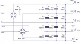
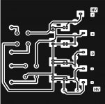
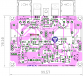
I hope this psu schematic and PCB layout for HX11 is correct please tell me if any errors
Regards
GPS
Regards
GPS
Attachments

Last edited:
Hi Apex thanks for sharing nice projects.
1 question about GND.
I see Sgnd and Pgnd.So Pgnd not getting connected to circuit i see,right?they have connection between 100nf only.
1 question about GND.
I see Sgnd and Pgnd.So Pgnd not getting connected to circuit i see,right?they have connection between 100nf only.
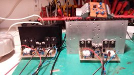
Hi,
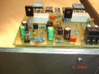
this is my AX-14 with 2 pairs 5200/1943 output and mje15032/15033 drivers. PSU is 2x53 VDC and 30mF per rail. It plays very well, strong bass and clear mid and high. Now I will try to build AX-11 with TO-3 transistors.
Hello zoky2
Nice build
I read your post #3361 on page 337
Can you share your two Pair AX-14 Schematics And Layout
Because I want to build it, I already make AX-14 with one pair, But wanted More power On 8Ohm load. Can Your two Pair AX-14 Amp gives you 120 To 130W on 8-ohm load, What is maximum Rail voltage it can handle, on 53Vdc+/- I think it gives you about 115W on 8Ohm load.
Please help me in details with your Two pair AX-14 Schematics And LAyout
Thanks
Best regards
Attachments
Last edited:
No, use 330R instead 560R for higher gain.
Hi!
How to change the input sensitivity? I want to decrease it. But I have noticed that there is one scheme with R8 = 560r, R2 = 22k and one with R8 = 22k, R2 = 560r. Which one is correct?
Thanks!

Gurpreet Turna it,s not best drawing this power supply try again the capacitors are too small ...
- Home
- Amplifiers
- Solid State
- 100W Ultimate Fidelity Amplifier