Hi Artosalo,
Aren't you missing a resistor to ground, either at the input or output to set a defined potential? I guess only one of the two would be required because of the unbypassed feedback?
Regards,
M.
Aren't you missing a resistor to ground, either at the input or output to set a defined potential? I guess only one of the two would be required because of the unbypassed feedback?
Regards,
M.
Yes, both resistors should be added.
But I already told at post #20 that the schematic
is having only components that are required for simulation and presenting the design idea.
But I already told at post #20 that the schematic
is having only components that are required for simulation and presenting the design idea.
Last edited:
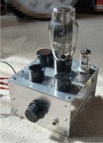
Here my version which I made a long time ago for my Sennheiser HD650 headphone. Did not yet take the time to
design a simple power supply for it.
Such a big output caps raising from the amplifier 🙂
I imagine you used an external PSU then
Here is another 6N13S headphone amplifier idea (=simulation so far) for low impedance headphones (32 ohms), now with White cathode follower.
Gain is 7.5 dB, Pout vs. THD at the schematic.
An externally hosted image should be here but it was not working when we last tested it.
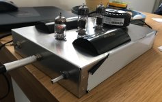
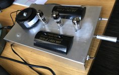
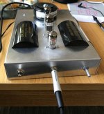
I have done this Arto’s design with 6N2P-EV and 2 x 6N6P tubes. I used a pair of Jantzen MKP 330 uF caps on the output and the bass response is quite remarkable with both Audeze LCD-2.2 and Senn HD800. Overall the sound quality is very promising though I haven’t listened to it that much yet.
Attachments
Such a big output caps raising from the amplifier 🙂
I imagine you used an external PSU then
I, at the time when I was building that amplifier, loved the idea of placing those caps that way. But time changed my view 🙂 .
Yes, you are correct with your imagination: I used a stabilized power supply for the amp and just an external simple heater transformer for the tube filaments.
The fact is that I am not using this amp nowadays. I am using a headphone amp with two EL84's, one for each channel. And in this case I indeed designed a supply for it
using the 85A2 stab tube.
I have done this Arto’s design with 6N2P-EV and 2 x 6N6P tubes. I used a pair of Jantzen MKP 330 uF caps on the output and the bass response is quite remarkable with both Audeze LCD-2.2 and Senn HD800. Overall the sound quality is very promising though I haven’t listened to it that much yet.
Wow! I love the way you placed those caps. Beautiful view.
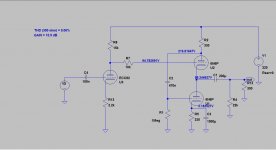
I tried a LTSpice simulation for a WCF with a different power tube, first time with a 6CG7 and then with 6N6P. I put the picture of the diagram for this last one.
It seems to work well with high impedance headphones, but also with NFB the THD is around 1% for a 32 ohm load. Instead with the 6CG7 (and NFB) the circuit seems to work well even with low impedance, with a THD of 0.3% with 32 ohm load, but I used a sort of voltage divider between first and second stage.
It seems to work well with high impedance headphones, but also with NFB the THD is around 1% for a 32 ohm load. Instead with the 6CG7 (and NFB) the circuit seems to work well even with low impedance, with a THD of 0.3% with 32 ohm load, but I used a sort of voltage divider between first and second stage.
Attachments
I was thinking about substitute the 6n1p for a 6sn7
Made a schematis for it...
It's my first one with tubes. I took Artosalo's suggestion as a basis and changed tube and value on couple of resistors.
How does the schematics look. Will this work.
I'm new to LT spice and have not figured out how to simulate yet

Made a schematis for it...
It's my first one with tubes. I took Artosalo's suggestion as a basis and changed tube and value on couple of resistors.
How does the schematics look. Will this work.
I'm new to LT spice and have not figured out how to simulate yet
Made a schematis for it...
You can use 6SN7 of course. But your circuit has odd component values.
2k7 at the anode of 6SN7 is very low. Why such value ? That makes the gain of this stage only 6 dB. Therefore, even without NFB, the overall gain of the whole amplifier is - 6 dB (negative). Secondly the voltage across the upper part of 6AS7 is only 25 V while it is some 90 V for the lower part.
What load impedance you plan to use with this amp ?
2k7 at the anode of 6SN7 is very low. Why such value ?
I used that value from another schematis... Is it better to use 47K?
What load impedance you plan to use with this amp ?
600ohm
But I would like to have the possible to use Low Z headphones on it
You can use 6SN7 of course. But your circuit has odd component values.
2k7 at the anode of 6SN7 is very low. Why such value ? That makes the gain of this stage only 6 dB. Therefore, even without NFB, the overall gain of the whole amplifier is - 6 dB (negative). Secondly the voltage across the upper part of 6AS7 is only 25 V while it is some 90 V for the lower part.
What load impedance you plan to use with this amp ?
Hi Arto, I planned a new schematic with WCF similar to yours except the preamp tube (with one I already have). Would you check it if I email the LTSpcice file? Thanks.
Hi Arto, I planned a new schematic with WCF similar to yours except the preamp tube (with one I already have). Would you check it if I email the LTSpcice file? Thanks.
I'm not Arto, but you should add a grid leak resistor to your ECC82 input valve. 100k ohms is a common value to use there.
--
I'm not Arto, but you should add a grid leak resistor to your ECC82 input valve. 100k ohms is a common value to use there.
--
Sorry, maybe I made a mistake 🙂
Anyway, I tried with a different tube: the E88CC. By ltspice simulation all seems to work better. I'll keep in mind your suggestion meantime.
I made some changes to my design.
It seems to work fine and with low distortion.
You have set R2 to 470 ohms and R3 470k. This means that there is practically no negative feedback.
Therefore, and because the amplifier already has low distortion, you can leave those resistor fully away.
I planned a new schematic with WCF similar to yours except the preamp tube (with one I already have).
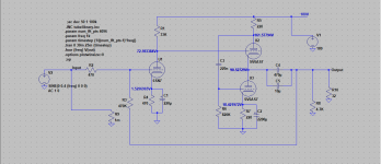
Here the circuit you sent (with E88CC) and that I modified:
- added 6N6P anode current to 28 mA with R5
- adjusted lower input impedance (47k) and lower NFB with R6 to get more suitable gain (...just my opinion)
- re-biased E88CC to lower anode voltage (with R13 and R8) to bias 6N6P so that both triode halves have same power dissipation
- adjusted R2 to set 6N6P lower stage AC-drive to optimum
Now the THD = 0.12 % at 13 mW to 32 ohms. Originally it was THD = 0.3 % at 6.5 mW to 32 ohms.
Attachments
Last edited:
- Home
- Amplifiers
- Tubes / Valves
- The 6N13S "Artosalo" OTL headphone amplifier