dear Alexmm sir
try to connect input gnd direct to psu
Also done that but no Chenge in dcout, pridriver transistor check also
Finally Ax 14 is workinng
I have make mistake place 547 instead 557
Now amp working bias is 13 mv
I have make mistake place 547 instead 557
Now amp working bias is 13 mv
Finally Ax 14 is workinng
I have make mistake place 547 instead 557
Now amp working bias is 13 mv
Nice! 😉
can anyone tell ,should I disconect SG wire to PSUG after bias is set ? because I read in some post back, that for only test connect wires .
can anyone tell ,should I disconect SG wire to PSUG after bias is set ? because I read in some post back, that for only test connect wires .
No, signal GND must be connected to psu GND alwayes.
No, signal GND must be connected to psu GND alwayes.
Ok
Amp working great no hum and clear sound but I feel low gain when I connected it on mobile .
I
Ok
Amp working great no hum and clear sound but I feel low gain when I connected it on mobile .
I
Yes, i have same find but you can increase the gain changing feedback network.
Yes, i have same find but you can increase the gain changing feedback network.
Hello Thimios
Can you tell me exactly which component I have to cheng to increase AX-14 amp gain without changing its stability.Rail voltage is +/-46vdc is it an ok or bit low for required voltage.
Thanks for helping me.
Best regards
Ok i will try to answer looking at my AX14.Hello Thimios
Can you tell me exactly which component I have to cheng to increase AX-14 amp gain without changing its stability.Rail voltage is +/-46vdc is it an ok or bit low for required voltage.
Thanks for helping me.
Best regards
Modification was according to Mile's suggestion.
PSU can be used for stereo amp, but beter use as dual mono.
Hello Apex sir
I have 4 capacitors 10000uf/50V, Can I use these in series to work with this PSU. I have 35-0-35VAC/400VA toroidal transformer.
Attachments
Last edited:
I also advice 63 volt caps.
You need to factor in the tolerance the mains supply. A rise in mains could make your DC supply higher than 50 volts. It is never a good idea to run components so close to their limits.
You need to factor in the tolerance the mains supply. A rise in mains could make your DC supply higher than 50 volts. It is never a good idea to run components so close to their limits.
Increase wattage
Hi,
Greetings of the day.....
Posting here a multisim file and the original document, I request the experts in our forum to have a look and possibility to increase the wattage to say 100w with minimal alterations.
Thanks and regards.
Anoop.🙂
Hi,
Greetings of the day.....
Posting here a multisim file and the original document, I request the experts in our forum to have a look and possibility to increase the wattage to say 100w with minimal alterations.
Thanks and regards.
Anoop.🙂
Attachments
Help if required someone About AX-14
Hello DIYers
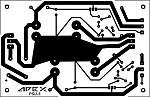
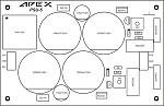
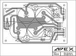
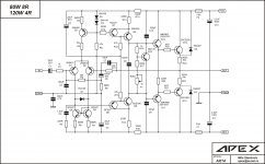
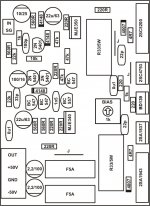
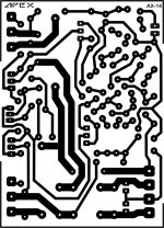
I am posting some information about building AX-14 Amp.I attach schematics, PCB bottom layout and top with a component orientation which I use during building this amp.I am using one pair semantics.Use these schematics if you want only one pair of an output transistor.
For biasing connect
Input GND to PSU GND and short an input signal to GND
DC offset voltage must be in mV
use 10R/10W resistor instead of fuses.
if you want to have a bias of 50mA...
V=IR; ohm law
V=50mA*0.33Ohm
V=16.5mvolts
Place your DMM negative probe to GND. and Positive to R33/5W or Emitter of 2SC5200/2SA1943 and adjust 1K trimmer to 15mV DC.
as per suggestion, the bias is between 15mV to 20mV (50mA to 60mA bias).
if you have trouble setting the bias, you may need to change R16 from 1k to 1.5k.
if you have an unstable bias, you may need to install Zobel network on output, that connects output and ground with 4.7R/2W resistor in series with a 100nF/100V capacitor
Replacement for transistor
2SA1478/2SC3788, or 2SB649 and 2SD669... can be used instead MJE340/MJE350, a replacement for 2SC4793 AND 2SA1837 is 2SA1306/2SC3298
2SC2336/2SA1006 can be used as drivers for AX-14.
2SC2922/2SA1216 can be used for AX-14 without changing anything.
And please read the thread for more information If you want to success AX-14 amp without much trouble.
Thanks
Best regards
Hello DIYers
I am posting some information about building AX-14 Amp.I attach schematics, PCB bottom layout and top with a component orientation which I use during building this amp.I am using one pair semantics.Use these schematics if you want only one pair of an output transistor.
For biasing connect
Input GND to PSU GND and short an input signal to GND
DC offset voltage must be in mV
use 10R/10W resistor instead of fuses.
if you want to have a bias of 50mA...
V=IR; ohm law
V=50mA*0.33Ohm
V=16.5mvolts
Place your DMM negative probe to GND. and Positive to R33/5W or Emitter of 2SC5200/2SA1943 and adjust 1K trimmer to 15mV DC.
as per suggestion, the bias is between 15mV to 20mV (50mA to 60mA bias).
if you have trouble setting the bias, you may need to change R16 from 1k to 1.5k.
if you have an unstable bias, you may need to install Zobel network on output, that connects output and ground with 4.7R/2W resistor in series with a 100nF/100V capacitor
Replacement for transistor
2SA1478/2SC3788, or 2SB649 and 2SD669... can be used instead MJE340/MJE350, a replacement for 2SC4793 AND 2SA1837 is 2SA1306/2SC3298
2SC2336/2SA1006 can be used as drivers for AX-14.
2SC2922/2SA1216 can be used for AX-14 without changing anything.
And please read the thread for more information If you want to success AX-14 amp without much trouble.
Thanks
Best regards
Attachments
Last edited:
Hi,
Bias is measured across the emitter resistor and not across emitter and gnd. Please correct.
V= I*0.33 for positive side or negative side emitter resistor=16.5
Or V= I*0.66 across both positive and negative emitter resistors=33mV
Could be a typo error in your post, so thought to let you know
Bias is measured across the emitter resistor and not across emitter and gnd. Please correct.
V= I*0.33 for positive side or negative side emitter resistor=16.5
Or V= I*0.66 across both positive and negative emitter resistors=33mV
Could be a typo error in your post, so thought to let you know
Last edited:
Hi,
Bias is measured across the emitter resistor and not across emitter and gnd. Please, correct.
dear prasi
What I say is If you want to check bias voltage on 0.33Ohm register your DMM black probe must connect amp GND and positive probe on the 0.33Ohm resister.
No, that is not the correct way to measure bias. Bias is measured "across" emitter resistor. + or red Probe to emitter side of the resistor and - or black probe of DMM to "speaker out" side of the resistor. It should measure the voltage drop across emitter resIstor and hence the current flowing through it.
Unless you want to convey something else, which I am not able to understand.😉
Unless you want to convey something else, which I am not able to understand.😉
Last edited:
- Home
- Amplifiers
- Solid State
- 100W Ultimate Fidelity Amplifier