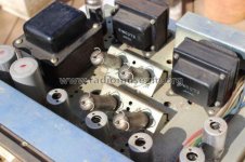
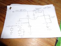
I managed to pick up a non-operational DIY EL84 PP amp. It has some nice vintage iron - an Engel 350V transformer, two Partridge 8000:3.5 output transformers, and a 10H, 200Ω 180mA choke. It had 2xEL84 output valves per channel, with ECC81 and ECC82 as pre and phase splitters, and an unidentified rectifier (probably 5U4 based on connections). The original circuit has some quite unusual features and component values (e.g. 15k screen resistors). I have decided to redesign and rebuild it completely, including a new chassis. So I'm going to go for a straightforward EL84 PP amp, using ECC83s for pre/splitter and GZ34 for rectifier (valve choices due to availabilty and familiarity). I also want to put a phono stage in. I have a Lite MV02 IR remote control kit to put in too.
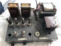
I want to do something different from the standard valves-at-the-front-transformers-at-the-back layout (I have a very nice one already), and came up with this more vertically-oriented idea:

But before I do the new chassis I will get the circuit design done and tested before investing that cost and effort. More to come

I want to do something different from the standard valves-at-the-front-transformers-at-the-back layout (I have a very nice one already), and came up with this more vertically-oriented idea:

But before I do the new chassis I will get the circuit design done and tested before investing that cost and effort. More to come
Power Supply:
The power supply is pretty standard, with an idea from the original circuit, which had a separate supply for each pre/splitter stage, and I've added one for the phono. I will finalise the component values once i know the currents of all stages, but it will probably be R1 = 100-150Ω, C1 & C2 = 30uF, maybe the other caps too. I am looking for a main supply of 320V-325V, since that seems about the upper limit when biasing the EL84s (see later) with the 8000Ω output transformer. The secondary supply of 300V is somewhat arbitrary, but is convenient because many datasheets show ECC83 valve performance at 300V.
I did consider a choke input power supply, but the data sheets suggested to me that the supply voltage would be below 300V at the likely current of around 120mA.
Attachments
Nice tfmr's. Although I can relate to your wanting to do things differently as regards layout, I'd be wary about mounting valves on their sides. Some valves have info about mounting on their datasheet's and suggest certain orientation, but I can't find anything on a quick look at the valve datasheet's you intend using. Might be an idea to use screening can's for the IP valves and socket spring "clamps" for the other's.
Re the PSU, de-coupling the IP and phase splitter's is a good idea. After reading Morgan Jones tests on the 6SN7 family of valves, including the ECC82, see page 188 Valve amplifiers, I've been looking at using 6CG7's and other twin triodes instead of ECC82's, though I've done no tests. Just throwing out some thoughts.
There is some interesting ideas and circuits here - Phase inverters. the idea being to get as low as possible THD on the front end and phase splitter as well as good PS frequency response.
Good luck, A.
I don't know for how much you got that amp but just the Partridge OPT are usually expensive. Anyway, that's an interesting project.
I had an amp, ( I think it was an American Channel Master ) that had it's EL84s mounted at an angle of 45deg. to reduce headroom I suppose.
check these:
http://www.collinsradio.org/wp-content/uploads/2015/05/6BF5-vs-6AQ5-for-Heat-Reduction_Edited.pdf
Tube Amp Facts
Personally, I wouldn't build a tube amp the way you've pictured it. Hot air rises & the tubes would get hotter, faster than a regular build, (vs the transformers under the tubes as pictured).
But it's your decision. YMMV
Last edited:
I think the tubes might run cooler in that configuration. At least the glass would since there is unimpeded air flow around the tube from the 'bottom' up unlike an upright tube that has the chassis blocking flow.
Also, the vast majority of tubes that can't be installed like this are filamentary cathode tubes that are capable of sagging. The 5U4 is a perfect example. Datasheet says horizontal operation only as long as pins 1 and 4 are vertical to each other.
Also, the vast majority of tubes that can't be installed like this are filamentary cathode tubes that are capable of sagging. The 5U4 is a perfect example. Datasheet says horizontal operation only as long as pins 1 and 4 are vertical to each other.
Thanks all for the comments and advice - that's what makes this forum so good! 🙂
As a general response, I've looked around a lot, and all of the valves I want to use can be mounted any way according to their datasheets. It apparently starts becoming an issue with larger valves like EL34s where the grids can sag and short out, but not so much with the so-called "minature" valves. But i will convert those existing chassis into a mock-up of the proposed layout to test. My thinking was in line with kylej1050 - that the airflow would be good around the valve. But ChrisABC has a good point about the upper valves - would the air from the EL84s below overheat them? I'll have to see.
Thanks DA - that's a good reference for phase inverters - I'll post my design ideas later and that will help a lot. I'll check out the 6SN7s too.
crazyfrog - I paid R1500, which is about US$125 for the amp
Soonerorlater - like this one? Channel Master 6601 - cool
Attachments
Output Stage:
Since the transformers are a given, i thought I should tackle the output stage next. The B+ has been set at 320V (could be revised if needs be). The Partridge OPTs don't have ultralinear taps, so I'm going for pentode mode. I am considering putting a pentode/triode mode switch in, so I'll calculate for that too.
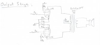
So looking at the Class B loadline for the 8000Ω OPT (i.e. 2000Ω load), it seems to me that 320V is about the upper limit. Choosing 25 mA as the quiescent current gets us just to the maximum dissipation envelope, putting the bias point on the Vg1 = -12V line. The mutual characteristics curve says the screen current will be 4mA or so. So the cathode resistor Rk = 12/(25mA+4mA)= 414Ω (use 390 or 430Ω - EIA E24 standard value). So would I be correct to say that I need up to 12V to -12V swings from the phase splitter?
Some questions:
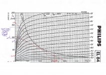
Calculating the screen resistor Rs is less easy. Looking at other EL84 amps out there, you see anything from no resistor to 100Ω to 1kΩ, even as high as 15kΩ (!) in the amp as it stands now. Now I understand the reason for the resistor. The best explanations are in the various guitar amp sites (why? 🙁) - they seem to advocate really squashing the grid curves down, but they love distortion (the purple scribbling on the grid graph was from earlier "thinking"). To me it seems as though you want the minimum for hifi to reduce non-linearity, yet still protect the screen? So I am going to go for an uninformed 100-200Ω pending enlightenment. I haven't even started thinking about triode mode yet.
I'm also not too sure about the number I got for Ck, the cathode bypass cap. Based on the mutual conductance curves, I estimated the transconductance of the valve to be 12.9 mS. In parallel with the cathode resistor Rk, the resulting cathode impedance is 65Ω. A 200 uF cap gives a cutoff frequency of 12Hz, a 100 uF, 24 Hz. I haven't seen many higher than 200uF, so i feel happy with that range.
I have seen some amps with a common Rk and Ck for both valves - any thoughts on that? I would halve the resistance and double the capacitance.
Since the transformers are a given, i thought I should tackle the output stage next. The B+ has been set at 320V (could be revised if needs be). The Partridge OPTs don't have ultralinear taps, so I'm going for pentode mode. I am considering putting a pentode/triode mode switch in, so I'll calculate for that too.

So looking at the Class B loadline for the 8000Ω OPT (i.e. 2000Ω load), it seems to me that 320V is about the upper limit. Choosing 25 mA as the quiescent current gets us just to the maximum dissipation envelope, putting the bias point on the Vg1 = -12V line. The mutual characteristics curve says the screen current will be 4mA or so. So the cathode resistor Rk = 12/(25mA+4mA)= 414Ω (use 390 or 430Ω - EIA E24 standard value). So would I be correct to say that I need up to 12V to -12V swings from the phase splitter?
Some questions:
- Most other designs seem to have have a lower bias current - is 25mA too high?
- Could/should I make HT+ higher and move the load lines a bit to the right for more oomph? (I am more interested in sound quality - i have other amps if i want power)

Calculating the screen resistor Rs is less easy. Looking at other EL84 amps out there, you see anything from no resistor to 100Ω to 1kΩ, even as high as 15kΩ (!) in the amp as it stands now. Now I understand the reason for the resistor. The best explanations are in the various guitar amp sites (why? 🙁) - they seem to advocate really squashing the grid curves down, but they love distortion (the purple scribbling on the grid graph was from earlier "thinking"). To me it seems as though you want the minimum for hifi to reduce non-linearity, yet still protect the screen? So I am going to go for an uninformed 100-200Ω pending enlightenment. I haven't even started thinking about triode mode yet.
I'm also not too sure about the number I got for Ck, the cathode bypass cap. Based on the mutual conductance curves, I estimated the transconductance of the valve to be 12.9 mS. In parallel with the cathode resistor Rk, the resulting cathode impedance is 65Ω. A 200 uF cap gives a cutoff frequency of 12Hz, a 100 uF, 24 Hz. I haven't seen many higher than 200uF, so i feel happy with that range.
I have seen some amps with a common Rk and Ck for both valves - any thoughts on that? I would halve the resistance and double the capacitance.
I have some transformers that look identical (at least visually) to yours. They are P3667 with 8k primary (plus 6k taps) and two 3.5 ohm secondaries (3.5 ohm in parallel, 15 ohm in series). If you are going to run the output in pentode mode (which is what I have done) I would recommend a regulated screen supply for lowest distortion. I stole the design from SY's red light district.
25mA doesn't look particularly high, steady state dissipation is 8 watts which is quite conservative. I know the load line crosses the 12W limit, but on average the dissipation will be less. I used 470 uF for the cathode bypass capacitors, higher is better but you have to watch out for overload recovery time constant.
25mA doesn't look particularly high, steady state dissipation is 8 watts which is quite conservative. I know the load line crosses the 12W limit, but on average the dissipation will be less. I used 470 uF for the cathode bypass capacitors, higher is better but you have to watch out for overload recovery time constant.
A few thoughts on your OP stage. Is your 320v HT/B+ figure loaded or unloaded? HT drops obviously with a load so it may be less than 320v.
The Mullard EL84 datasheet - page 2 gives a 270 ohm Rk, Ik 36mA for HT 300v Z pri 8k Pout 17w, which is pushing it, but gives you a rough idea. To find R G2 the same table gives Ig2 as 11mA so that gives you R G2 as 27 to 29k or Ia max divide by I G2 max = 4, so a ratio of 4:1. See - The Valve Wizard -Small Signal Pentode
As regards your G1 - G1 of 12v (24v) this will be the open loop figure, it will change with NFB applied. The best advice I can give, is to make your IP and PS gain as high as possible with as low THD as you can. This gives you gain/headroom to throw away later with NFB applied.
All these figures and those you gave arn't set in stone and may need changing on the actual build. I'd advise using separate Rk and if possible put in a pot so you can adjust the Ik/balance if you have one. A linear dual gang 100 ohm pot say (needs to be high wattage) in the cathode circuit would allow you to adjust balance of the OP stage. Better balance = better THD, this goes for the PS OP too. However that's for later.
Andy.
I have some transformers that look identical (at least visually) to yours. <snip>
Thanks for the transformer part number tikiroo - that looks exactly like mine, except for the 6kΩ taps which mine doesn't have (I neglected to mention earlier that mine also have the 15Ω speaker taps). The only number on mine is D3098, which doesn't bring anything up on google. Maybe they were custom made for some amp maker?
Regarding the cathode bypass, my initial calcs also threw up that high number using Valvewizard's methodology, and I thought it too high because I didn't see a similar value on any of the many other amps I looked at, so that's encouraging. It's something I can play with when I test.
I had a look at the Red Light circuit - some nice ideas there. I was thinking of testing constant current circuits to bias, but like some of those tricks...
A few thoughts on your OP stage. Is your 320v HT/B+ figure loaded or unloaded? HT drops obviously with a load so it may be less than 320v. <snip>
Thanks Andy - I'm aiming for 320V quiescent, so with no signal.
Regarding the Rg2, I did at first use Valvewizard and came up with 5kΩ, but I haven't seen such high values on EL84 power stages on any cicuits I've looked at - mostly they're 100-500, max 1000Ω, so I thought there must be a reason. Suddenly a regulated Vg2 is staring to make sense.... 😀
But your point is noted - all values can be experimented with to get the best result. That's half the point of DIY, isnt it?
Check the typo in the power supply. Choke should be 10H not 10uH!
Errr.... yes indeed - 10H. 😕
You could just make a loop or two in the wire to get 10uH!
R G2 is there to regulate G2 Pdiss and G2 Vmax which according to Valve Wizard's method is 1/4 of max anode diss and according to the Mullard EL84 datasheet is 300v. So your G2 resistor needs to drop 20v.
I used 11mA off the datasheet earlier 300/0.011 = 27,272 or 27k, but this doesn't seem right. It's a while since I've done this, the last amp I built was UL which is different. Looking at it another way to drop 20v @ 11mA would need a 1k8 but 7mA is more usual so a 2k8 is the figure I get. Had a quick look at the Mullard 5-10 and there they use a 47 ohm. Go figure.
But as you say screen grid regulation is a good idea, though it adds complexity. There is a circuit called the Long Tailed Cascode Pair by L B Hedge, there is a version as used on the Dynaco ST70, see ST70 with solid state regulation by Joe Curcio - Glass Audio, there he uses SS regulation for the screen grid. I couldn't find a copy online, drop me a PM with your email address and I'll send it you.
His PSU was quite complex being servo controlled and the LTCP is a bit over the top to drive two EL84's, but might be worth a look at.
One last comment regarding CCS as used on LTP's etc. I've had good results, but also had problem's with terrible ripple rejection on one amp I built. Might be an idea to get the amp working with resistors and unregulated screen supply's and go from there.
A.
I agree that I should get it going old-school first and then only start try fancy tricks.
I'll give the screen resistor more thought. A popular method seems to be to take it off the main supply via a resistor, with a cap to ground, or for it to have its own C-R-C pi between the main and secondary supply (that's how the Mullard 5-10 does it). Some take it from the secondary supply.
I'll give the screen resistor more thought. A popular method seems to be to take it off the main supply via a resistor, with a cap to ground, or for it to have its own C-R-C pi between the main and secondary supply (that's how the Mullard 5-10 does it). Some take it from the secondary supply.
And some use a cheap shunt regulator (dropping resistor and VR tube or Zener)
My experience says any 9 pin tubes can have the screen powered by a 1k/47uF RC network. KT88 etc on the other hand I find sound better with a stabilized screen supply.
My experience says any 9 pin tubes can have the screen powered by a 1k/47uF RC network. KT88 etc on the other hand I find sound better with a stabilized screen supply.
A screen resistor is doing two jobs; 1) It's there to keep G2 diss max to specs and maybe drop HT/B+ 2) It's there to stop oscillation. Either way, it should be connected as close to the pin as possible with very short lead to keep down stray inductance.
I've knocked up a sketch to clarify. X is R G2, suppression grid not shown.
Andy.
I've knocked up a sketch to clarify. X is R G2, suppression grid not shown.
Andy.
Attachments
Signal drive increases only for the stage where the NFB signal is applied to, i.e. where the NFB loop signal subtracts from the input signal. So, signal drive requirements for the finals will solely change if NBF is applied locally to these, say cathode NBF or UL mode, but not for GNFB.As regards your G1 - G1 of 12v (24v) this will be the open loop figure, it will change with NFB applied. The best advice I can give, is to make your IP and PS gain as high as possible with as low THD as you can. This gives you gain/headroom to throw away later with NFB applied.
Best regards!
Koda would you take that from the B+/HT or the secondary supply, and is the cap from screen to gound?And some use a cheap shunt regulator (dropping resistor and VR tube or Zener)
My experience says any 9 pin tubes can have the screen powered by a 1k/47uF RC network. KT88 etc on the other hand I find sound better with a stabilized screen supply.
That's pretty much how the mullard 5-10 does it, with the exception of the cap from screen to ground. But looking at that configuration, when the screen current is high, it is not dropping the supply voltage to the input and phase splitters? I'd be more inclined to take it from B+. But anyway, my head is spinning from all this - I've thought more about this bloody screen supply/resistor than anything else. I'll just build something and fiddle around then....A screen resistor is doing two jobs; 1) It's there to keep G2 diss max to specs and maybe drop HT/B+ 2) It's there to stop oscillation. Either way, it should be connected as close to the pin as possible with very short lead to keep down stray inductance.
I've knocked up a sketch to clarify. X is R G2, suppression grid not shown.
Andy.
PS - thanks for the Joe Curcio article - great read.
Last edited:
- Status
- Not open for further replies.
- Home
- Amplifiers
- Tubes / Valves
- EL84 PP design

