Thank's X,
The amp is a keeper.
But not like the Monster you have just brought to life.
I can only wonder how the BB sounds as the A20 with the Tannoys is Very loud at 12 oclock more than enough to give you permanent hearing loss.
Huge sound stage with Authority!!!
Keep up the good work.
Steve.
The amp is a keeper.
But not like the Monster you have just brought to life.
I can only wonder how the BB sounds as the A20 with the Tannoys is Very loud at 12 oclock more than enough to give you permanent hearing loss.
Huge sound stage with Authority!!!
Keep up the good work.
Steve.
Thank's Hugh,
Yes they are some of Julians heatsinks MF35 151x350 and warm to the touch.
The inputs are 80mm from the outputs do you think they are too close.
Hugh you have designed a Superb Amp Many Thank's.
Steve.
Yes they are some of Julians heatsinks MF35 151x350 and warm to the touch.
The inputs are 80mm from the outputs do you think they are too close.
Hugh you have designed a Superb Amp Many Thank's.
Steve.
Steve,
My pleasure, I'm thrilled you like it - the trailblazer with most of my ideas is X, and I'm forever grateful to him. I'm an old codger, not so energetic and while I love the design, the implementation leaves me wanting......
Do you live in Melbourne?
Hugh
My pleasure, I'm thrilled you like it - the trailblazer with most of my ideas is X, and I'm forever grateful to him. I'm an old codger, not so energetic and while I love the design, the implementation leaves me wanting......
Do you live in Melbourne?
Hugh
There’s not much you can do about the spacing on the MOSFETs as that is set by the PCB and it follows the UMS spacing on the DIYA store heatsinks. The spacing seems just fine on my A20 amp - with temps around 40C. No hot spots. That Conrad heatsink looks really nice.
Thanks for the kind words, Hugh. But for me it is quite a privilege to be able to be the first to hear your creations. It sure is a lot of fun though.
Thanks for the kind words, Hugh. But for me it is quite a privilege to be able to be the first to hear your creations. It sure is a lot of fun though.
Another Hybrid Aleph Lives!!!
Steve,
Congratulations on the birth of your new ALPHA20!!
It looks perfectly at home in that enclosure, nice job 🙂
Cheers,
Vunce
Hugh,
I grew up in Melbourne But now live in Tasmania on the East coast.
I'm nearly the wrong side of sixty so your not on your own.
Steve.
I grew up in Melbourne But now live in Tasmania on the East coast.
I'm nearly the wrong side of sixty so your not on your own.
Steve.
Thank's Vunce,
Still need to tidy up the wiring and the transformer is 325VA and is getting a little warm but i have another the same so might use one per channel.
How are you liking your A20.
Steve.
Still need to tidy up the wiring and the transformer is 325VA and is getting a little warm but i have another the same so might use one per channel.
How are you liking your A20.
Steve.
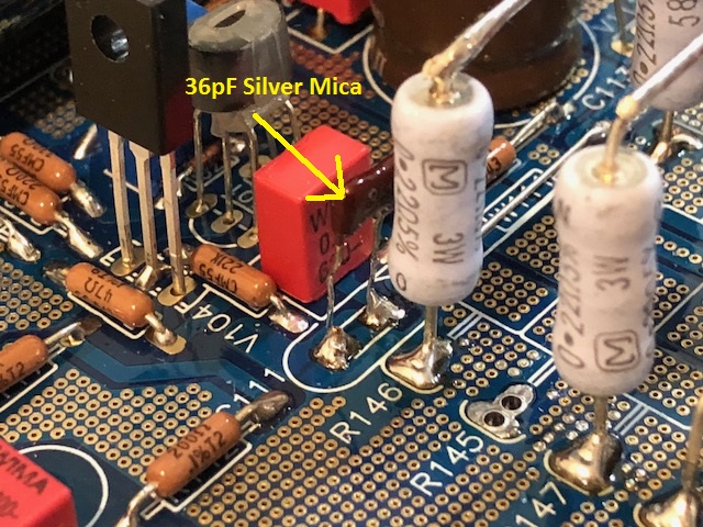
Alpha BB Amp - 36pF C111, a Transformation
After listening extensively to my test tracks I felt that some of the 3d spatial imaging was a bit soft focus. Hugh had told me earlier that setting the feedback cap C111 was critical to this and had to be determined by experimentation. It needs to be high enough to avoid oscillation, but not so high that the imaging suffered. Anyhow, the design called for nominally a 47pF value. I had 33pF+22pF NP0 there for 55pF (8pF above nominal). I looked through my bins and found some 36pF silver mica. I swapped the NP0's out for the smaller 36pF silver mica. Glad I did, it really made an audible difference. On my test tracks that I use for spatial imaging, the sounds were suddenly crisply 3 dimensional and I could accurately locate the instruments on the stage with my eyes closed. In addition, the dynamics seem to be more forceful. So overall, quite a transformation to an already amazing sounding amp.
After listening extensively to my test tracks I felt that some of the 3d spatial imaging was a bit soft focus. Hugh had told me earlier that setting the feedback cap C111 was critical to this and had to be determined by experimentation. It needs to be high enough to avoid oscillation, but not so high that the imaging suffered. Anyhow, the design called for nominally a 47pF value. I had 33pF+22pF NP0 there for 55pF (8pF above nominal). I looked through my bins and found some 36pF silver mica. I swapped the NP0's out for the smaller 36pF silver mica. Glad I did, it really made an audible difference. On my test tracks that I use for spatial imaging, the sounds were suddenly crisply 3 dimensional and I could accurately locate the instruments on the stage with my eyes closed. In addition, the dynamics seem to be more forceful. So overall, quite a transformation to an already amazing sounding amp.
Attachments
Usully trimcap can be used., adjust when its good read value and solder yourAfter listening extensively to my test tracks I felt that some of the 3d spatial imaging was a bit soft focus. Hugh had told me earlier that setting the feedback cap C111 was critical to this and had to be determined by experimentation. It needs to be high enough to avoid oscillation, but not so high that the imaging suffered. Anyhow, the design called for nominally a 47pF value. I had 33pF+22pF NP0 there for 55pF (8pF above nominal). I looked through my bins and found some 36pF silver mica. I swapped the NP0's out for the smaller 36pF silver mica. Glad I did, it really made an audible difference. On my test tracks that I use for spatial imaging, the sounds were suddenly crisply 3 dimensional and I could accurately locate the instruments on the stage with my eyes closed. In addition, the dynamics seem to be more forceful. So overall, quite a transformation to an already amazing sounding amp.
silver mica or......
Last edited:
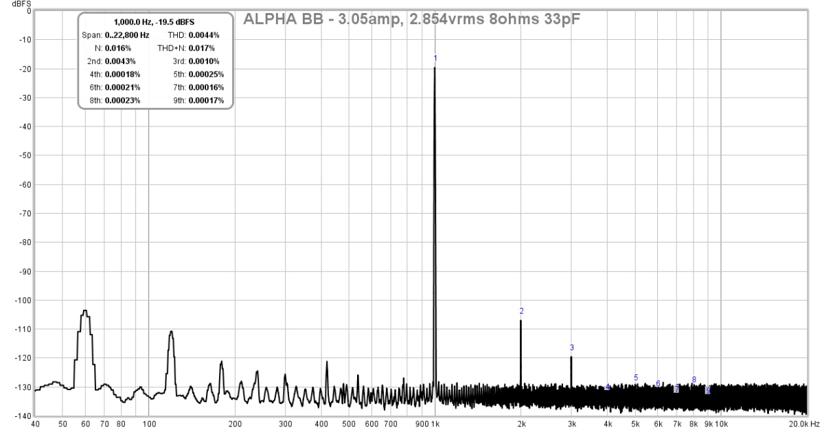
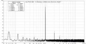
I looked at the signal on an O-scope and the smaller 36pF cap is not causing any oscillations. The FFT's look good too.
Here is 2.85vrms into 8ohms, THD is 0.0044% and dominant H2 and some H3:
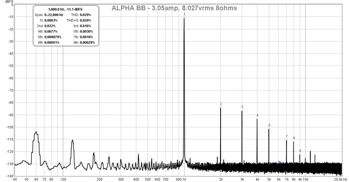
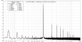
Here is 8.02vrms into 8ohms, THD is 0.029% and dominant H2 and descending profile:
Here is 2.85vrms into 8ohms, THD is 0.0044% and dominant H2 and some H3:
Here is 8.02vrms into 8ohms, THD is 0.029% and dominant H2 and descending profile:
Attachments
X,
They are very good results...... but as the output increases, the THD (predictably) increases too, but even so the profile is maintained with H2 always dominant over H3.
Thank you for testing out the compensation. This is a very important aspects to sonics, yet it hardly affects THD. You hear it clearly; but it does not show up on THD. That tells us something very important, that we may be measuring the wrong things....
HD
That's very interesting the effect of the fb cap on spatial imaging.
So the quality of spatial imaging of an amp is something we don't know how to measure and is not completely related to low distortion.
Makes sense for me, with the amps that I have, some have higher distortion but throw a much better soundstage.
Hugh,
for the 4R version with reduced gain shunt fb 2.7k+47uf,
I have changed the gain to be a little higher with shunt fb 2.2k+56uf
It looks a little better in the simulations, also the ratio H1-15/H1-4
But for the fb compensation cap do I leave it at 22p ?
I don't know how to simulate this for oscillations.
Regards,
Danny
Hi X,
nice work !
The FFTs look good, especially for high sensivity speakers 😉
I think I'll make a CLC PS to get rid of the 50Hz,
in simulations the negative rail is much more sensitive to 50Hz than the positive rail, in the positive rail there's the CCS for extra filtering.
nice work !
The FFTs look good, especially for high sensivity speakers 😉
I think I'll make a CLC PS to get rid of the 50Hz,
in simulations the negative rail is much more sensitive to 50Hz than the positive rail, in the positive rail there's the CCS for extra filtering.
Hi X,
You're running the BB with reduced voltage rails due to your transformer problems.
Probably when you have higher voltage rails the FFT will look better.
Whenever I tried to reduce the voltage rails on the Alpha20, distortion went up.
For the Alpha20 24v is really recommended.
I didn't study this on the BB, probably it needs also the recommended voltage rails for lower distortion.
Hi Danny,
You are limited with compensation cap calculation in Spice. You are dead right, this spatial aspect is not measured in audio and therefore conventional thinking is that it is not important, the arrogance of conservatism! People say Spice can calculate compensation caps; I have found that listening tests are more definitive, though the simulation will indicate something within +/-30%. You can do a Bode graph of course, but the Spice engine does not take account of the parasitics in the board, and certainly does not fully describe the active devices, or even the HF performance of the electros. Ergo - take an educated guess with Spice, then fiddle up and down, listening careful for spatial cues, particularly with a large orchestra well recorded.
When you increase the Closed Loop Gain, you decrease the loop gain, increasing higher levels of low order and decreasing high order. Correspondingly, if you decrease CLG you increase loop gain, that is, increase the levels of global feedback, and this creates more error correction of higher orders, leading to more distortion of H5 and beyond. I try to get H5 below -100dB, and so clearly here you have a balancing act, like just about any other machine in the physical world.
You could try 22pF, 30pF and 36pF and have a listen! I cannot tell you what is ideal, but clearly this cap will be dominated not just about the loop gain but also by the target impedance, that is, the shunt fb resistor. 2k2 will need more cap than 2k7, of course.
HD
Last edited:
Thanks Hugh,
I'll do that by listening,
I'll install something so that I can easily change the value of the fb compensation cap.
Now we only need a stage imaging measurement tool,
that would be helpful 🙂
I'll do that by listening,
I'll install something so that I can easily change the value of the fb compensation cap.
Now we only need a stage imaging measurement tool,
that would be helpful 🙂
Hi, my reflection:
In the real world, amplifiers usually work between 8 and 10 watts with sensitivity speakers around 90 dB.
It would be very interesting if the harmonic profile measurements were always made at 1 watt (for reference, like the SNR) and 8 watts.
-> ALPHA 20 harmonic profile with 8 watts?
In the real world, amplifiers usually work between 8 and 10 watts with sensitivity speakers around 90 dB.
An externally hosted image should be here but it was not working when we last tested it.
with random phase: 92.5 dB
It would be very interesting if the harmonic profile measurements were always made at 1 watt (for reference, like the SNR) and 8 watts.
-> ALPHA 20 harmonic profile with 8 watts?
Last edited:
Hi Maty,
Using 22k/1k5 giving a gain of 15.7 [23.9dB], 8R load at 1KHz, I get H2 -76dB, H3 -85dB, H4 -101dB and H5 -111dB. THD is 0.0189%. Power is 8.2W [+18.5dBU], 22.5Vpp, but of course these are simulations. X may be able to measure, and generally his figures seem to be better than the simulations.
At 1W the figures are a little different, but only a little. For 8Vpp output, H2 -85dB, H3 -98dB, H4 and beyond right at the noise figure and THD of 0.00612%.
These are commendable figures, but I really look at ratio of summed distortion of H2+H3+H4 over complete THD, should be more than 99.5%, indicating very, very low part of the THD is actually H5 and beyond. I also like to check the ratio of H2 amplitude over H5; this ratio should be higher than 15. These are just rules of thumb, but I have found that they indicate strongly that an amp will sound pretty good since it inclines distortion towards monotonic decreasing.
HD
- Home
- Amplifiers
- Solid State
- Aksa Lender P-MOS Hybrid Aleph (ALPHA) Amplifier