But MLCC is always smallish, like 100nF max, too small for most coupling uses, so are you sure they are COG/NPO?
The system no matter how big or how small, how clean or how dirty, how flat or not needs to have the right groove.It is the music that moves you, not the low THD, not the damping factor, not the flat freq response. Music that connects to you, that moves you, does so whether played through the high end system or played through the kitchen radio.
What constitutes the 'right groove' is a subject in itself...hint, listen for the noise.
Dan.
But MLCC is always smallish, like 100nF max, too small for most coupling uses, so are you sure they are COG/NPO?
My question too; are they perhaps X5R or X7R? These are known to be horribly non-linear.
Jan
@vacuphile: some nice numbers from some simple tweaks (and evil electrolytics). I could be temped by a brace of those as an upgrade on my system at some point.
But MLCC is always smallish, like 100nF max, too small for most coupling uses, so are you sure they are COG/NPO?
Oh no and no, MLCC are up to 4.7uF (please check Murata catalogue e.g.) and maybe more, and they are not only COG/NPO, but also X5R, X7R etc. The capacitance is nonlinear and also DC bias dependent, it can fall to 20% of original value. I only do not understand how someone could/can use it in an audio product..... Armchair design?
Bout COG or NPO are quite linear and can be used with no problems. It's the other dielectrics that are so bad, and those are used for the high values.
Jan
Jan
Yes but the caps I speak about are not COG/NPO. High capacitance + small dimensions = X7R.
Please see the attached catalogue graph of ac nonlinearity (source - Murata catalogue).
I measured similar curve at 40 years old Tesla ceramic cap. But I would never expect audio designer to put this into signal path. I would not do it even 40 years ago.
Please see the attached catalogue graph of ac nonlinearity (source - Murata catalogue).
I measured similar curve at 40 years old Tesla ceramic cap. But I would never expect audio designer to put this into signal path. I would not do it even 40 years ago.
Attachments

Last edited:
What changes objectively and subjectively when the ideal zero ohms loading is not quite ideal ?.The ESS9018/38 do prefer to be loaded with a virtual GND instead of using for ex a resistor as load. Performance from the 9018/38 is the best being loaded with 0 Ohms.
Yes, needs to be bloody good, one that does not get upset with high levels of digital/ultrasonic content, iow needs to be a powerful, ie a really good integrator.The new 9038 outputs a lot of current if driven in mono mode, about 160mA AC. To make an IV converter for it having zero Zin is a bit like making a small power amp....
That should be of no consequence, what are you getting at standard average music levels ?.Originally Posted by john curl View Post
I glad to see that several of you are serious about discrete I-V converters for the OPPO, etc. Most everyone, except for the tube guys seem to be stuck with IC's, except us! '-)
I am using something more close to the schematic that I put up recently, and finally got the distortion below 0.01% nearly pure third harmonic at full output digitally.
(Have you had a listen yet ?.)
DAC design: the I/V stage WARNING: TECHNICAL CONTENT
Dan.
Last edited:
It is the music that moves you, not the low THD, not the damping factor, not the flat freq response. Music that connects to you, that moves you, does so whether played through the high end system or played through the kitchen radio.
Jan
So you never experienced that the same record did actually make more music through different system components or version of them?
//
Hi Jo, (Rasmussen), quite a while back IRC you mentioned using supercaps for bypassing DAC/OPS supplies....what are your longer term conclusions ?.For quite a few years I used a simple resistor and got great results. But then in my experiments I noticed that making the power supply to the DAC chip better (i.e. lower impedance) made the sound even better. I scratched my head for a very long time as to why this might be and eventually came to the realization that the ability of the particular DAC chip I was using to reject power supply noise was dependent on the impedance presented by the following I/V stage to its output. In EE parlance, the PSRR of the DAC is improved with reduced output compliance.
Dan.
Oh no and no, MLCC are up to 4.7uF (please check Murata catalogue e.g.) and maybe more, and they are not only COG/NPO, but also X5R, X7R etc. The capacitance is nonlinear and also DC bias dependent, it can fall to 20% of original value. I only do not understand how someone could/can use it in an audio product..... Armchair design?
I was aberroneously equating MLCC to COG/NPO. The X7R are miracles indeed. Got 1 uF from Samsung hardly larger than a spec of dust.
Are you at liberty to tell us which product you found this in?
@Scott
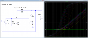
Here are simulations of my model based on the AD797 data sheet fig 33.
I've not chosen gm with any care but it doesn't affect the nature of the system. I gave the output buffer 100 ohms resistance to set an impedance floor to make the same hockey-stick shape as for the JCX model. In the first plot I also included a 1Mohm "parasitic" resistance from node B to ground. This is the only way to keep the thing from oscillating when Cc=Cn=50pF. In the second plot, the 1M is removed. Note that Cn is set negative here (to avoid the complexity of a current mirror).
Plot 1:
Output Z, closed loop, 1M damping resistor.
The important observation is that as Cn approaches |50pF| the Z knee increases in f but it remains a 1st order slope, 20dB/dec. This is what the mathematics predicts. So the appearance of a 40dB/dec slope in the full op-amp model is due to other circuit components not in the simplified model. As Cn approaches Cc the loop loses stability and will oscillate when there is no 1M resistor to damp it. The green line shows Cn=Cc. Obviously, the full model is very stable and this is again due to parasitics/components not included in the simplified model.
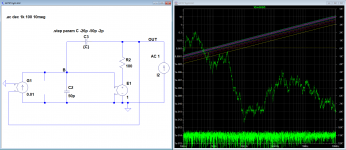
Plot 2:
Same as plot 1 but with no 1M resistor.
Plot 3:
This shows the loop gain of the Cn feedback loop with no global feedback. You can see how the gain increases rapidly as Cn approaches Cc.
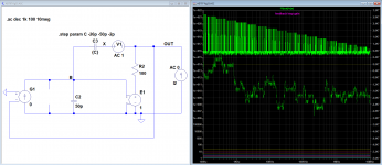
I don't think the Theory of Operation in the data sheet is a strictly accurate description of what happens in the op-amp. This should not be a surprise because "error cancellation" by feedback is impossible except hypothetically in academic's margin notes.
I need to think to what extent a self-bootstrapping circuit like this reduces its own distortion. It will reduce output Z. But I cannot find a graph in the data sheet of THD vs f with and without Cn; which is a curious omission considering the theory of operation claims distortion cancellation as a benefit of Cn.
Here are simulations of my model based on the AD797 data sheet fig 33.
I've not chosen gm with any care but it doesn't affect the nature of the system. I gave the output buffer 100 ohms resistance to set an impedance floor to make the same hockey-stick shape as for the JCX model. In the first plot I also included a 1Mohm "parasitic" resistance from node B to ground. This is the only way to keep the thing from oscillating when Cc=Cn=50pF. In the second plot, the 1M is removed. Note that Cn is set negative here (to avoid the complexity of a current mirror).
Plot 1:
Output Z, closed loop, 1M damping resistor.
The important observation is that as Cn approaches |50pF| the Z knee increases in f but it remains a 1st order slope, 20dB/dec. This is what the mathematics predicts. So the appearance of a 40dB/dec slope in the full op-amp model is due to other circuit components not in the simplified model. As Cn approaches Cc the loop loses stability and will oscillate when there is no 1M resistor to damp it. The green line shows Cn=Cc. Obviously, the full model is very stable and this is again due to parasitics/components not included in the simplified model.
Plot 2:
Same as plot 1 but with no 1M resistor.
Plot 3:
This shows the loop gain of the Cn feedback loop with no global feedback. You can see how the gain increases rapidly as Cn approaches Cc.
I don't think the Theory of Operation in the data sheet is a strictly accurate description of what happens in the op-amp. This should not be a surprise because "error cancellation" by feedback is impossible except hypothetically in academic's margin notes.
I need to think to what extent a self-bootstrapping circuit like this reduces its own distortion. It will reduce output Z. But I cannot find a graph in the data sheet of THD vs f with and without Cn; which is a curious omission considering the theory of operation claims distortion cancellation as a benefit of Cn.
Attachments
Last edited:
White cats with yellow eyes tend to be deaf.
As to conscious awareness and women, I will not fall into that trap again.
We had a cat with yellow belly, he went running at the slightest sound.
Pavel, did you mean to say these are COG/NP0? In a later post you said you weren't talking about that type. Just wanted to be clear because I haven't heard reports of high distortion in this type before.Oh no and no, MLCC are up to 4.7uF (please check Murata catalogue e.g.) and maybe more, and they are not only COG/NPO, but also X5R, X7R etc. The capacitance is nonlinear and also DC bias dependent, it can fall to 20% of original value. I only do not understand how someone could/can use it in an audio product..... Armchair design?
Oh, sorry, I was obliged to leave suddenly, and had not time to re-read before leaving. I wanted to say the contrary:I could say that, when we listen to the "sound", we, indeed, do NOT listen to music.Interesting remarks.
I could say that, when we listen to the "sound", we, indeed, do listen to music. (and that is where a lot of audiophiles are ;-).
I apologize.
Of course. One of the place where a lot of people prefer to listen to music is in their car.It is the music that moves you, not the low THD, not the damping factor, not the flat freq response. Music that connects to you, that moves you, does so whether played through the high end system or played through the kitchen radio.
Hifi is another kind of pleasure, more physical ...
Assuming that voltage is the voltage across the cap, not the applied signal voltage, then with a large enough cap value and a small enough signal you might get away with it for mid-fi equipment. I am not recommending this!PMA said:Yes but the caps I speak about are not COG/NPO. High capacitance + small dimensions = X7R.
Please see the attached catalogue graph of ac nonlinearity (source - Murata catalogue).
I measured similar curve at 40 years old Tesla ceramic cap. But I would never expect audio designer to put this into signal path. I would not do it even 40 years ago.
If the above conditions are not met then you get 3rd order distortion with no DC bias and 2nd order with DC bias. It is fortunate that opamp circuits with bipolar supplies don't put much DC across coupling caps. Traditional discrete circuits with unipolar supplies may need better coupling caps (with regard to dielectric linearity) than modern stuff.
Thanks Dan for the links. Everything helps.
PMA, eureka! You have found what mid fi designers (like Sony) actually use as coupling caps. This (ceramic coupling caps) is what I had to replace in my Sony tuner with comparable electrolytic caps.
However, 50 years ago, I did not know the sonic damage that a high Q ceramic could do, and I tried them out, only to remove them later, after hearing a problem. Of course, the manufacturer did not give any warning in the data sheet.
The most revealing way to understand how really bad a hi Q ceramic is, can be done by modifying a semiconductor curve tracer to map a cap's path with a varying voltage.
Tektronix showed it to me first in 1974 and it was very revealing. You drive the cap with a triangle wave and have it differentiate to a 'square' on the curve tracer screen. Not only SEVERE non-linearity is seen, but actually 'non-return to zero' can appear. I have never found a worse measuring cap than a hi Q ceramic of 1uf more or less.
@Scott
Here are simulations of my model based on the AD797 data sheet fig 33.
First you expect with nothing but ideal sources and reactances (Zo = inf or 0) you would get a singularity at DC this is not an instability but an artifact of simulation.
Secondly I already said the 1/f squared behavior is from ft limitations and failure to perfectly bootstrap at high frequencies. Take two vectors same amplitude opposite sign and subtract them, now take the small angle approximation for the difference as the phase of one changes around 0. In any case your plot shows the improvements.
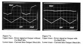
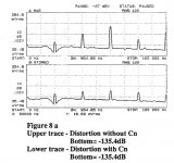
Here is a plot of both Zout and the crossover being reduced. Tri-wave stimulus is a powerful tool when looking at op-amps with first order compensation. The errors are proportional to the derivative so tri-waves make square wave errors. The bumps are the derivative of the crossover (little hats). This has been discussed before, this presentation shows clearly how crossover creates frequencies higher than the stimulus and that the spectral shape approaches a train of pulses (that furry floor on THD plots). This is actually at G=100 (to magnify the effect) and shows current forced into the output to only exercise the buffer's Zo and crossover error.
The THD plot is complicated by the fact that there were analyzers available and that that in this test the limit imposed by the input LTP was -110dB, still this is -105dB almost a 20dB improvement.
The substantial improvement is obvious. So what do you want to argue that nothing is really there, something else has been sacrificed that we are hiding? A gain of 100 pre-amp has 1Mhz BW with or without Cn, there is no effect on slew-rate or any other performance specs.
Attachments
Last edited:
- Status
- Not open for further replies.
- Home
- Member Areas
- The Lounge
- John Curl's Blowtorch preamplifier part III