Current sources
Since I am not familiar with designing amplifier circuits, can anybody tell me
how the current sources (for excample the tail current source) do look like in detail
in terms of a schematic.
Thank you for support.
Since I am not familiar with designing amplifier circuits, can anybody tell me
how the current sources (for excample the tail current source) do look like in detail
in terms of a schematic.
Thank you for support.
hi Max!
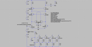
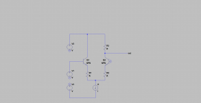
these are my old plays with Peufeu's memdist, the idle is ~90mA
cheers!
Hi Pavel. Thanks very much. I am unable to simulate. Could you please do the following to resurrect your interest:
1) 1K resistor on the emitter of the "second BJT" (PNP) from the CFP (emitter to output node of the CFP-source of the JFET), this way the gain is reduced and the offset is minimal.
2) Can you do the cascoded-cascode VAS, with a 22R to 50R between the first cascoded elements?
This is the way Peufeu planned it. Look at the schematics above.
3) I do not understand your feedback. 🙁
Can you do a cascoded-CFP also at the output and have a conventional feedback? When I cascoded the outputs, they became stable.

Edit: look at the interesting PDF attached about Bias circuit.
Hi JOSI1,
Please take a look at:
Current Sources, Sinks and Mirrors in Audio
Cheers,
M.
Attachments
Last edited:
Hi Max!
do not get me wrong, I only wanted to show you a few posts before that the memdist amp is possible (in theory) to build.
The figures are not so bad but due to memdist triples at the input and cascodes it might be marginal stable.
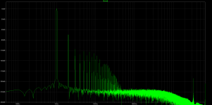
I attached for you the results of the sims after the changes proposed by you, it looks like thd spectrum has more hf harmonics.
2k7 resistor of cfp pair is the value given from the God to get the lowest thd from cfp pair.
I attached before the asc file to tease you to get yourself ltspice, which is for free, and try your own ideas.
I will watch the thread with the interest but please do not expect me to check your ideas with the simulator,
cheers!
do not get me wrong, I only wanted to show you a few posts before that the memdist amp is possible (in theory) to build.
The figures are not so bad but due to memdist triples at the input and cascodes it might be marginal stable.
I attached for you the results of the sims after the changes proposed by you, it looks like thd spectrum has more hf harmonics.
2k7 resistor of cfp pair is the value given from the God to get the lowest thd from cfp pair.
I attached before the asc file to tease you to get yourself ltspice, which is for free, and try your own ideas.
I will watch the thread with the interest but please do not expect me to check your ideas with the simulator,
cheers!
Attachments
Hi Pawel,
Yes, you're right. At this stage of my career I must learn how to use those tools...
The problem is that I use Ubuntu at home...
I place the 1K R in the other BJT's emitter, for lowest offset. With simulators I could find the best CFP option and explore all the possibilities of cascodying different outputs, indeed.
Thanks for your interest.
M.
no problem, LTSpice works great through the wine,
tested by me with Ubuntu, Mint, Chatleau!
but only the old version, new VIII has the issues.
tested by me with Ubuntu, Mint, Chatleau!
but only the old version, new VIII has the issues.
well, LTP is a kind of Rush cascode with the transistors of the same sex,
when the first is emmiter follower steering the second common base via its emmiter,
does it reduce memdist?
I would say yes!
Does it improve SQ?
I do not know!
when the first is emmiter follower steering the second common base via its emmiter,
does it reduce memdist?
I would say yes!
Does it improve SQ?
I do not know!
Attachments
Last edited:
Please explain to me what this is all about.
I was expecting to see something about stability of the bias at the output stage of a class aB amp.
I see this thread is mostly about input stage and VAS, I do not understand since those are class A stages known about no temperature effect from audio. May be at very low frequencies where junction temperature time constant could matter.
I must be missing something, buried in many lengthy threads and references.
Please give me the basis on this memory distortion.
does it reduce memdist?
I would say yes!
Does it improve SQ?
I do not know!
Test it. It's easy and inexpensive. 😉
I already modified 4 circuits: 3 amps and 1 DAC output. The effect is comparable and constant.
Cher mchambin.
I am also exploring output sections. Mainly cascodying-cascadying the big units. As I said, it is difficult to say if the improvement in transparency, dynamics and timbres are due to improved linearity or to thermal memory (or other thermal) effects...
I am accumulating energy to make the next experiments...cascodying the already cacode-VAS, using a CFP-cascode output...etc.
Best wishes,
M.
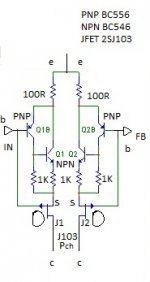
The following is the schematic of the units to replace PNP differential amplifier for the input sections of the Blame and of the Sony TA-5650 amps.
I added an extra resistor to the "follower" BJT. These resistors' position and value are not optimized for reduced THD: simply used to get negligible offset.
Feel free to comment or advice better strategies.
I added an extra resistor to the "follower" BJT. These resistors' position and value are not optimized for reduced THD: simply used to get negligible offset.
Feel free to comment or advice better strategies.
Attachments
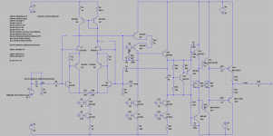
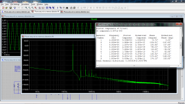
My simulation of headphone amplifier using this concept:
THD at 4,5V peak, 20kHz, 33 Ohm = 0.000051%.
Attachments
My simulation of headphone amplifier using this concept:
THD at 4,5V peak, 20kHz, 33 Ohm = 0.000051%.
Nice.
Do you have Frequency response and phase plots?
Thanks for your contributions.
M.
100mA bias?
About 150mA.
I lowered the THD a bit with changing the compensation.
Nice.
Do you have Frequency response and phase plots?
Thanks for your contributions.
M.
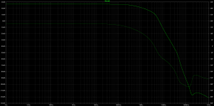
This is close loop small signal frequency response.
Attachments
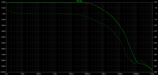
This is close loop small signal frequency response.
Great. Thanks.
I am still doing my first essays with low complexity circuits and learning the basic functions slowly...
I can see the mod as it is could sound too "dark" to some.
M.
OK. Quick update.
(sorry guys, I can only evaluate sound by listening to music)
First, I increased current for the Blame's differential input section from 2,09 to 3,24mA, per side, after reading this interesting site:
Ovation e-Amp: A 180 Watt Class AB VFA Featuring Ultra Low Distortion
They way I did it was paralleling a 300R to R4, with minor adjustment for DC offset on one channel. 😎
Probably more dynamic sound...
Second, I finally did the cascoded-CFP mod for the already modded cascaded/cascoded output. Since it was already modded, I just added a PNP (D45H11; different encapsulation) to the 5200 NPN, as follower of the Sziklai pair, with a 10R from 5200's C to D45H11's E. It worked flawlessly,
Guys, you really have to try these mods...
I will continue my listening session today, but so far the effect is very impressive.
I now think that transistors are gregarious animals that like to share the work we ask from them 😀
Apart, I had some delay due to problems on one channel: pops and strange noises and fluctuation in DC output for several mV. I tapped on top of components and finally found the culprit: C7 from feedback resistor to "ground" was leaky. I replaced it for a good quality one (higger VDC) and everything is perfect now. I also swapped C8 for a better quality one. I now recommend myself to populate the boards (even experimental circuits) with the best quality available. Not only it will sound better but one probably will be saved from lots of troubles and headaches...
Cheers,
M.
- Home
- Amplifiers
- Solid State
- The AMNESIS amp: a good amplifier, like a gentleman, has no memory.