done.
connected a speaker and it plays music. sounds good. no disortions. not loud but ok.
the driverboards is ok it seems.
so need to test it again.
what are the pros here recimmending?
thx
regards
slavko
connected a speaker and it plays music. sounds good. no disortions. not loud but ok.
the driverboards is ok it seems.
so need to test it again.
what are the pros here recimmending?
thx
regards
slavko
Now you need to investigate what is happening with the bias. Using a multi-meter measure the voltage between the two points which connect to the output boards. Using the bias trimmer you should be able to reduce the voltage below 1.2V, the point where the output transistors turn on. If you can do it, it is now safe to connect the output devices. If the voltage does not drop, you need to verify the corresponding portion of the main board.
hi again.
thx for your help.
measured between output and the npn/pnp outputs. ninimum voltage was 1,23V. i couldn't get below that.
does it sound ok or is there a fault?
thx
slavko
thx for your help.
measured between output and the npn/pnp outputs. ninimum voltage was 1,23V. i couldn't get below that.
does it sound ok or is there a fault?
thx
slavko
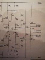
Check the resistor values in the Vbe multiplier.
Check the orientation/type of transistor in the Vbe multiplier.
Check the traces into/out of the Vbe multiplier.
Checking the Bias Voltage across the Vbe multiplier is important.
You should be able to turn it low enough to NOT turn ON the first stage of the outputs.
Each stage of a multiple EF output stage needs approximately 1.1Vdc to 1.2Vdc to start turning ON.
Thus, it is better if the Vbe multiplier gives a low setting of <1.0Vdc and can turn up enough to provide Vre at the set point recommended for the output devices. You can check this without the output devices connected.
Last edited:
hi.
i checked the resistors again. all looks good and the values are good.
i am using:
Q9 + Q11: 2SA968
Q10 + Q12: 2SC2238
Q13 + Q14 + Q16: MJE15030
Q15 + Q17: MJE15031
everything looks good to me except, that i can´t turn the voltage between output and npn/pnp below 1,23V.
regards
slavko
i checked the resistors again. all looks good and the values are good.
i am using:
Q9 + Q11: 2SA968
Q10 + Q12: 2SC2238
Q13 + Q14 + Q16: MJE15030
Q15 + Q17: MJE15031
everything looks good to me except, that i can´t turn the voltage between output and npn/pnp below 1,23V.
regards
slavko
Hi,
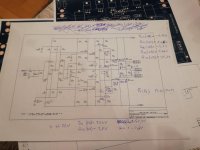
if you have not yet bought VR2 then I suggest some lower values for R36, R37 & VR2.
R36=430r
R37=2k4
VR2=1k
The bias current through Q13 is about 17mA and the resulting base current will be about 0.2mA.
The current through the resistor string R37 VR2 R36 is of a similar value. Ir36=0.65/R36~=0.65/1k5=0.43mA, when bias is set to maximum. Resistor current falls to just 0.2mA when VR2 is set to 1k75.
A small change in Q13 base current will have a very significant effect on the current passing through R37 and the resulting multiplication ratio will swing (unstable?) when Q13 base current varies.
Using reduced values for the resistor string will help to keep the multiplication ratio nearer to a constant value. Reducing R36 from 1k5 to 430r increases the maximum resistor current from 0.43mA to 1.5mA. This is still well within the current limit of a 300mW 1k multi-turn pot.
There may be an advantage to going even lower with these resistor values.
would this maybe help with my problem AndrewT?
regards
slavko
That is from some years ago and I had forgotten about my comments and recommendations.
I doubt I was wrong at that time so I have no reason to go back on my original recommendation, except maybe use a 2kVR to give a wider range of adjustment.
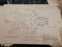
You can analyse the Vbe multiplier. It only needs simple arithmetic to determine the minimum Vbe multiplier Bias voltage and the maximum bias voltage from that set of resistors and VR.
The voltage regulator gain is [R37/{R36+Vr}+1] and by multiplying by Vbe you get the bias voltage
When VR=5000 ohms, the bias voltage is at minimum and equals 7500/{1500+5000} + 1 = 2.15*Vbe.
This is greater than the lower Vbe I gave in my earlier post.
It is my opinion this needs to be changed.
The maximum is 6*Vbe.
This set of simplified calculations ignores the effects of base current from Q13. The actual bias voltage will depend on the transistor hFE and the VAS current. That was the main reason for my lowered value suggestions. The low resistor values reduces dependence on device parameters.
I doubt I was wrong at that time so I have no reason to go back on my original recommendation, except maybe use a 2kVR to give a wider range of adjustment.
You can analyse the Vbe multiplier. It only needs simple arithmetic to determine the minimum Vbe multiplier Bias voltage and the maximum bias voltage from that set of resistors and VR.
The voltage regulator gain is [R37/{R36+Vr}+1] and by multiplying by Vbe you get the bias voltage
When VR=5000 ohms, the bias voltage is at minimum and equals 7500/{1500+5000} + 1 = 2.15*Vbe.
This is greater than the lower Vbe I gave in my earlier post.
It is my opinion this needs to be changed.
The maximum is 6*Vbe.
This set of simplified calculations ignores the effects of base current from Q13. The actual bias voltage will depend on the transistor hFE and the VAS current. That was the main reason for my lowered value suggestions. The low resistor values reduces dependence on device parameters.
Last edited:
made some measurement.
strange things happened.
i didn´t change anything and powered up the mainboard without anything connected to the output and npn/pnp connection.
pot fully turned clockwise (max bias):
Voltage between output and npn/pnp: 2,35V
Q14 VBE: 0,6V
Q16 VBE: 0,6V
Q13 VBE: 0,61V
Q17 VBE: 0,56V
Q15 VBE: 0,56V
pot fully turned anti clockwise (min bias):
voltage between output and npn/pnp: 1,2V
Q14 VBE: 0,53V
Q16 VBE: 0,53V
Q13 VBE: 0,61V
Q17 VBE: 0,54V
Q15 VBE: 0,56V
that doesn´t look good to me...
anybody any idea?
thx
regards slavko
now i changed to r37 // 10k and r36 // 1k8 (thank you andrewt) and the output went down to 700mV. i think this really helped with my problem.
will try with outputs tomorrow.
thx
slavko
will try with outputs tomorrow.
thx
slavko
hi
after powering up one side with an variac transformator, i have a good output signal until 200VAC.
after passing 200VAC the amp starts to swing at about 2.5 MHz.
does anybody have an idea how to stop the swing?
thx.
after powering up one side with an variac transformator, i have a good output signal until 200VAC.
after passing 200VAC the amp starts to swing at about 2.5 MHz.
does anybody have an idea how to stop the swing?
thx.
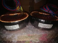
trafo psu
hello, I'm reading this forum x Ksa 100mkII, I think we were talking about using a 37-0-37 transformer from 900 / 1000w at least, now I from an old project I have 2 transformers from 600w 37x2, are not good to use x monoblocks? thank you😕
hello, I'm reading this forum x Ksa 100mkII, I think we were talking about using a 37-0-37 transformer from 900 / 1000w at least, now I from an old project I have 2 transformers from 600w 37x2, are not good to use x monoblocks? thank you😕
Attachments
pcb
HELLO, MAYBE I LOST IN THE FORUM BUT, I DO NOT SEE X FILES CREATE PCB X KSA100 MKII, HAVE YOU? thank you🙂
HELLO, MAYBE I LOST IN THE FORUM BUT, I DO NOT SEE X FILES CREATE PCB X KSA100 MKII, HAVE YOU? thank you🙂
hi.
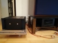
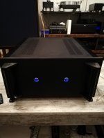
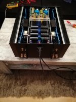
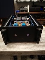
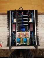
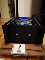
my amp is now up and running.
i had to change the capacitor from 20pF to 5pF over the feedback resistor.
now everything is working properly.
i reduced the bias to 0,25mA (=4A). makes about 80W class A.
thank you for this great amplifier. sounds great.
regards
s.
my amp is now up and running.
i had to change the capacitor from 20pF to 5pF over the feedback resistor.
now everything is working properly.
i reduced the bias to 0,25mA (=4A). makes about 80W class A.
thank you for this great amplifier. sounds great.
regards
s.
hello, I'm reading this forum x Ksa 100mkII, I think we were talking about using a 37-0-37 transformer from 900 / 1000w at least, now I from an old project I have 2 transformers from 600w 37x2, are not good to use x monoblocks? thank you😕
should be okay. i used 2 x40V (1000VA)
Photos
here are some photos of my finished amp...
here are some photos of my finished amp...
Attachments
-
 IMG_20180218_144632_resized_20180304_021237372.jpg903.3 KB · Views: 358
 -
 IMG_20180218_022853_resized_20180304_021234987.jpg615.9 KB · Views: 441
 -
 IMG_20180217_224359_resized_20180304_021235602.jpg960.4 KB · Views: 464
 -
 IMG_20180217_224347_resized_20180304_021234288.jpg797.5 KB · Views: 688
 -
 IMG_20180217_224340_resized_20180304_021236439.jpg373.6 KB · Views: 710
 -
 IMG_20180219_185204_resized_20180304_021238002.jpg711.3 KB · Views: 364
hi, but you would not have gerber or pdf x play the pcb? thank you😀here are some photos of my finished amp...
- Home
- Amplifiers
- Solid State
- Krell KSA 100mkII Clone