
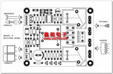
A quick clarification regarding my front panel LED switch which is connected to my thermal protection soft start module as in like "Softstart Module".
I connected the first 2 wires from top as in the pic of the soft start module to the 3rd and 4th pin which by the way I checked with the shorting indicator from the DMM. Then I used the remaining 3 wires from the next to the remaining 3 pins of the switch for LED. The issue I have is that when my wallwart socket plug is switched on I see that the LED switches on and then when I press the LED the amp switches on but when I again push it nothing happens and the amp which is supposed to switch off does not. But if I push it again the amp switches off but the LED is on till I power off the wallwart socket. This LED switch is breaking my head in terms of how to wire up as this is something new compared to the usual 2 pins top and the bottom 3 pins on the LED switch.
Any pointers will be much appreciated.
Thanks
Attachments
A quick clarification regarding my front panel LED switch which is connected to my thermal protection soft start module as in like "Softstart Module".
I connected the first 2 wires from top as in the pic of the soft start module to the 3rd and 4th pin which by the way I checked with the shorting indicator from the DMM. Then I used the remaining 3 wires from the next to the remaining 3 pins of the switch for LED. The issue I have is that when my wallwart socket plug is switched on I see that the LED switches on and then when I press the LED the amp switches on but when I again push it nothing happens and the amp which is supposed to switch off does not. But if I push it again the amp switches off but the LED is on till I power off the wallwart socket. This LED switch is breaking my head in terms of how to wire up as this is something new compared to the usual 2 pins top and the bottom 3 pins on the LED switch.
Any pointers will be much appreciated.
Thanks
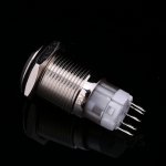
two of the tabs, most likely the outer two are to be used to power the led indicator, look carefully with a magnifying glass there should be a + and - sign in the plastic near them, obey this polarity for the led to work. you might try using a 9 v battery to test. the other three are for the power switch, use your dmm to test. typically the center is hooked up and one of the other two is selected to make the circuit. one makes the circuit when the button is up, and the other when it is depressed. test so the led is lit when circuit is made.
Hi Manniraj,
I use the same softstarts. The LED they use, and is included, is a dual red/green led. So you have to figure out which 2 leads are activated when there is power on the softstart and it has not started, and when there is power on the softstart and it has started. That are the leads to use for your blue ring pushswitch LED.
Also only a momentary push switch giving a pulse can be used.
Is your soft start also smelly ??? The blue transformer on it is getting very hot and gives a plastic burned smell 🙁
two of the tabs, most likely the outer two are to be used to power the led indicator, look carefully with a magnifying glass there should be a + and - sign in the plastic near them, obey this polarity for the led to work. you might try using a 9 v battery to test. the other three are for the power switch, use your dmm to test. typically the center is hooked up and one of the other two is selected to make the circuit. one makes the circuit when the button is up, and the other when it is depressed. test so the led is lit when circuit is made.
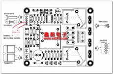
Yes correct I checked with the DMM and that the 3rd & 4th pins are for power switch, the outer pins are for LED lit. This from the power LED switch but when it comes to the soft start board the wiring has one extra wire for the LED which is supplied with the kit which I am not using and instead using those wires to power the front panel LED. The issue is that when the outer pins are connected on the LED switch they get lit when the wall wart plug is switched on. They are always on as long as the wall wart plug is on.
Hi Manniraj,
I use the same softstarts. The LED they use, and is included, is a dual red/green led. So you have to figure out which 2 leads are activated when there is power on the softstart and it has not started, and when there is power on the softstart and it has started. That are the leads to use for your blue ring pushswitch LED.
Also only a momentary push switch giving a pulse can be used.
Is your soft start also smelly ??? The blue transformer on it is getting very hot and gives a plastic burned smell 🙁
Thanks Walter, how do I test/check your statement "is a dual red/green led. So you have to figure out which 2 leads are activated when there is power on the softstart and it has not started, and when there is power on the softstart and it has started. That are the leads to use for your blue ring pushswitch LED." using the DMM or something else. Please clarify.
Not sure if its smelly and I have not checked if the blue small trafo gets hot during running of the amp. Will check and let you know when I open the top lid.
Thanks Walter, then the first 2 wires will be used for the switch on/off right? So I am going to leave the 3rd wire open not connecting to the LED switch!
Hello,
Quick question,
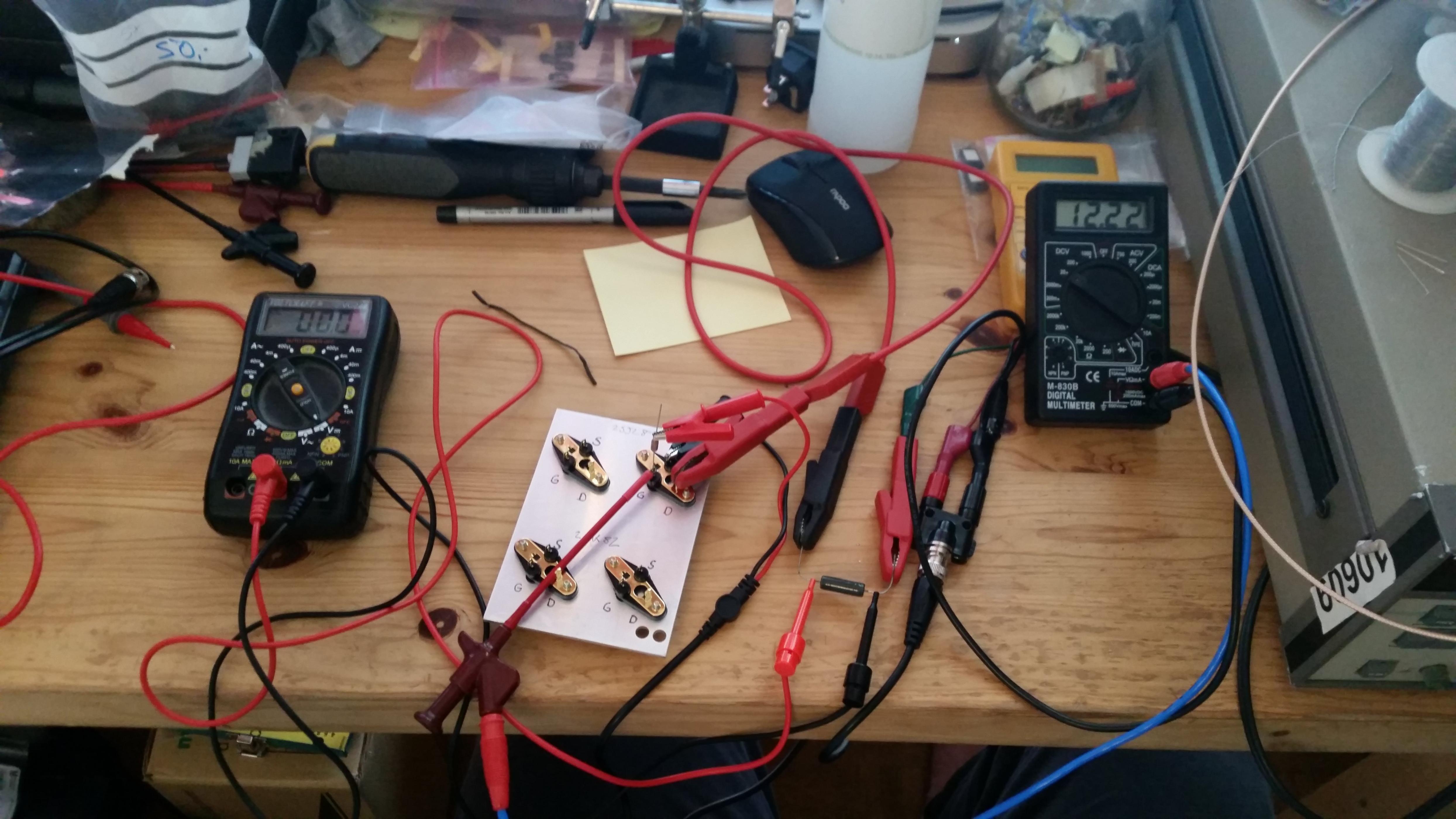
How do I test a pair of VFET’s. Managed to find a pair and want to check them out.
Best,
Andrew
Quick question,
How do I test a pair of VFET’s. Managed to find a pair and want to check them out.
Best,
Andrew
Whatever you do, the gate bias voltage MUST be present before applying the main supply voltage or you're at serious risk of frying the VFETs. They're self conducting and the bias voltage is needed to turn them off, thus limiting current through them.

Look at NP post 209 in this thread: http://www.diyaudio.com/forums/pass-labs/276711-sony-vfet-amplifier-2-a-post4392065.html
Is it necessary to mount the Fets on a heat sink for this?
Thanks
Sven
You will have 0.5A flowing in the resistor and also in the VFET. You have 18.5V over the same VFET => 9.25W in the VFET.
I used a metal plate to better spread out any heat generated during measuring V_gs. It can't hurt and reduces the risk of frying them, so given the scarcity of the part I'd say it's quite reasonable. Better safe than sorry.
I would think that the t-brackets supplied with the kit would work very well too.
I would think that the t-brackets supplied with the kit would work very well too.
Correct !
Hi Walter, yesterday I did the wiring based on your suggestion with +/- LED and now the LED glows correctly that it starts glowing only when pressed inside after switching on the amp. But the amp switching on with the push button still does not work correctly as I can see that the VFET amp boards + PSU boards LEDs glow a little bit even after I push the power LED button inside couple of times and in one of the pushes the amp switches off. The LEDs go off completely only after I switch off the wall socket power plug. Initially I thought that the caps might be draining slowly hence but today I saw that even after 40 to 45 mins all the 4 LEDs on the PCB boards were glowing slightly. Is that an issue with my LED power switch or the wiring is incorrect. I just followed the wiring which I posted in the previous posts and wired exactly.
- Home
- Amplifiers
- Pass Labs
- Sony vFET Amplifier Part 2