Don Keele's CBT technology is fascinating, and I've come very close to purchasing a pair from Parts Express. I heard them at CES a couple of times and they sound really good. They're the type of speaker that makes 'conventional' box speakers seem a bit silly.
But they're far from perfect. One big gripe that I have with the CBT design is that it requires an INSANE number of drivers to generate respectable output. The reason for this is because there is SIGNIFICANT power tapering in the CBT design.

Here's the power tapering of a CBT. Note that the drivers at the edge of the array get less than 10% of the power as the ones in the center.
This might be one of the reasons that the CBT technology has excited a lot of people on a theoretical basis, but you don't see a lot of these at concerts or in listening room: CBT shading reduces output when compared to a conventional array.
The other 'gripe' that I have with CBTs is that using resistors to do power tapering is kinda 'kludgey' IMHO. You're basically throwing power away to get the shading.
If DSP and amplification were free, then CBT is almost a no-brainer. And we're really getting to a point where good amps have never been cheaper. But an ideal CBT would require as many as 24 channels of DSP and power for a stereo pair. (Again, this would be an "ideal" CBT; the Parts Express CBTs are a compromise designed for home listening.)
But they're far from perfect. One big gripe that I have with the CBT design is that it requires an INSANE number of drivers to generate respectable output. The reason for this is because there is SIGNIFICANT power tapering in the CBT design.
Here's the power tapering of a CBT. Note that the drivers at the edge of the array get less than 10% of the power as the ones in the center.
This might be one of the reasons that the CBT technology has excited a lot of people on a theoretical basis, but you don't see a lot of these at concerts or in listening room: CBT shading reduces output when compared to a conventional array.
The other 'gripe' that I have with CBTs is that using resistors to do power tapering is kinda 'kludgey' IMHO. You're basically throwing power away to get the shading.
If DSP and amplification were free, then CBT is almost a no-brainer. And we're really getting to a point where good amps have never been cheaper. But an ideal CBT would require as many as 24 channels of DSP and power for a stereo pair. (Again, this would be an "ideal" CBT; the Parts Express CBTs are a compromise designed for home listening.)
The power tapering of the CBT impacts how loud it can play, and it requires you to purchase more drivers for a given SPL. IE, a conventional line array plays louder than a CBT with the same number of drivers.
So... why is the power tapering there?
The power tapering addresses the fundamental challenge with line arrays: when you have two loudspeakers with an unequal pathlength, the difference in arrival time causes comb filtering. The comb filtering is due to the difference in phase between the two sources.
Here's an example:
If you have two loudspeakers playing, and one has a pathlength that's 5cm longer than the other, you'll get a dip in response at 3400Hz. This is because 3400Hz is 10cm long, and the 5cm pathlength difference causes a null. (The two waveforms are 180 degrees out of phase.)
So the power tapering of the CBT strives to give you the best of both worlds: The big power handling of a line array, with a wavefront shape that approximates a point source. (Note that you'd need a two-dimensional CBT to mimic a point source; a 'typical' CBT behaves like a point source in one dimension.)

The way that the power tapering works is that the output of two units in the CBT array won't be particularly destructive, because the units at the edge are so strongly power tapered. For instance, the pathlength from the top of the array to your ears is significantly longer than the pathlength from the CENTER of the array to your ears. But because the driver at the top is so strongly tapered, the two units don't interfere with each other very much. A two-dimensional CBT array behaves a lot like a point source. But with a series of benefits that most points sources do not have:
3) high power handling
2) controlled directivity
1) CBTs have the potential to direct sound like a waveguide, but without the bulk.
Another 'neat' thing about CBTs, that might not be immediately obvious, is that you can manipulate the coverage and beamwidth by varying the delay and amplitude of the elements in the CBT array. In other words, just because a CBT has a curved surface doesn't mean that the wavefront has to match that curvature; you can adjust it dynamically, particularly if you have independent channels of amplification and DSP for the drive units.
So... why is the power tapering there?
The power tapering addresses the fundamental challenge with line arrays: when you have two loudspeakers with an unequal pathlength, the difference in arrival time causes comb filtering. The comb filtering is due to the difference in phase between the two sources.
Here's an example:
If you have two loudspeakers playing, and one has a pathlength that's 5cm longer than the other, you'll get a dip in response at 3400Hz. This is because 3400Hz is 10cm long, and the 5cm pathlength difference causes a null. (The two waveforms are 180 degrees out of phase.)
So the power tapering of the CBT strives to give you the best of both worlds: The big power handling of a line array, with a wavefront shape that approximates a point source. (Note that you'd need a two-dimensional CBT to mimic a point source; a 'typical' CBT behaves like a point source in one dimension.)
The way that the power tapering works is that the output of two units in the CBT array won't be particularly destructive, because the units at the edge are so strongly power tapered. For instance, the pathlength from the top of the array to your ears is significantly longer than the pathlength from the CENTER of the array to your ears. But because the driver at the top is so strongly tapered, the two units don't interfere with each other very much. A two-dimensional CBT array behaves a lot like a point source. But with a series of benefits that most points sources do not have:
3) high power handling
2) controlled directivity
1) CBTs have the potential to direct sound like a waveguide, but without the bulk.
Another 'neat' thing about CBTs, that might not be immediately obvious, is that you can manipulate the coverage and beamwidth by varying the delay and amplitude of the elements in the CBT array. In other words, just because a CBT has a curved surface doesn't mean that the wavefront has to match that curvature; you can adjust it dynamically, particularly if you have independent channels of amplification and DSP for the drive units.
The curvature of the CBT is meant to create delay for the drivers that are "farther back". Keele in one of his papers showed a non-curved system in which DSP was used to delay the signal to each driver, as needed, and the performance was the same, or better, than the curved version of the CBT.
The power tapering of the drivers is meant to mimic the power that would be radiated by a "wedge" cut from a sphere. This varies from the "poles" (where the wedge is narrow and tapers to a point) to the "equator" (where the wedge is widest). Assuming the same flux of acoustic energy per unit area, the power radiated by the "wedge" varies pole-to-equator, and to mimic this Keele tapers off the power to the the topmost driver (which is towards the "north pole" of the wedge). The driver at the floor is at the "equator" (the floor mirrors the top half acoustically to create the full "wedge") and so gets the "full power".
Keele is using a linear array to mimic a 3D sector of a sphere and the power tapering helps to make this work well. By using lots of drivers, the "tapering" can be done gradually. The system height and its shallow curvature are required to create the even power response and constant beam width up to a certain height that corresponds to the average height of an adult human. Many drivers are used because the width of the drivers must be small but they must also be spaced closely together.
As usual, I shamelessly copy other designs, and my idea to improve the CBT is based on a few things:
3) The Parts Express CBT 24 "Epique"
2) A few years back, an inventor patented a series of improvements to the Philips Bessel arrays. In a nutshell, the inventor used dual voice coil woofers to create a Bessel Array that behaved one way at high frequency, and a different way at low frequency.
1) The biggest influence by far was the JBL CBT arrays, the commercial ones
In a CBT, I think we can improve the design by having it power tapered at high frequency, but NOT at low frequency. As mentioned in post #2, a pathlength difference of just FIVE centimeters can create a dip at 3400Hz. So we definitely want to power taper at 20khz, 10khz, etc. But at 250Hz? No, we don't need power tapering at 250Hz. The wavelengths are so long, the pathlength difference between units isn't a big issue.
And the power tapering discards a great deal of output and efficiency. At 250Hz, or 125Hz, it would be really nice to get some of that efficiency back.
I think you are confusing some aspects of a linear array and comb filtering with the "sphereical cap" design basis for the CBT that utilizes power tapering. It's all spelled out in Keele's papers on the subject.
Okay, so if you've made it this far, you understand that the CBT array combines power tapering and array curvature to create a wavefront that mimics a point source, at least in one dimension.
The advantage of a straight array is that it can generate a lot of output due to a plethora of drivers; the disadvantage is that the elements interfere with each other. This is particularly problematic at high frequency, but isn't a big problem at low frequency.


Crossover filters introduce a delay, and the higher the order, the more the delay. The sims above illustrate how much delay is introduced by a Linkwitz Riley low pass filter.
In the graphs, you can see that the group delay at the crossover frequency increases almost 800% as you go from 2nd order to 8th order.
Hold that thought, because it's going to come in handy...
The advantage of a straight array is that it can generate a lot of output due to a plethora of drivers; the disadvantage is that the elements interfere with each other. This is particularly problematic at high frequency, but isn't a big problem at low frequency.
Crossover filters introduce a delay, and the higher the order, the more the delay. The sims above illustrate how much delay is introduced by a Linkwitz Riley low pass filter.
In the graphs, you can see that the group delay at the crossover frequency increases almost 800% as you go from 2nd order to 8th order.
Hold that thought, because it's going to come in handy...

Here's the idea that I came up with. It is basically a third order passive filter, but with a twist.
There are a total of five drivers in the "CBTish" array, but only one of the five drivers is playing full range. Two of the five drivers have a 3rd order lowpass, and the other two have a 1st order lowpass.
It's a strange looking filter, but it is cheap, and it accomplishes a few things that are important in a CBT:
1) With just four crossover components, this design lowpasses two of the drivers in the array at 2000Hz and two of the drivers at 8000hz.
2) By lowpassing the elements in the array, we get power tapering above 2000Hz, but no power tapering BELOW 2000Hz. This lets us "have our cake and eat it too." We get CBT behavior at high frequency, where it's essential to good high frequency response. But at low frequency, the array behaves exactly like a conventional line array.
If you'd like to play around with the xover topology, it is illustrated in the top left of the pic above. You can sim it in XSIM. (free!)
At the top right, you can see the individual responses of the various units, and their aggregate response. These drivers are 2" in diameter, and can accomodate a center-to-center spacing of approximately 2.5". In a conventional array, that spacing would cause some nasty comb filtering that starts around 5400Hz. But in this "CBTish" design, only one driver is playing at full volume above 5400Hz. The highs are power-tapered.
If you want to tinker with this, the topology is basically a third order filter, but with the array units wired in such a way that only two of the five drivers "see" the third order filter. (Note that the driver on the far left of the topology is receiving a full range signal.)
Patrick,
So are you thinking a bunch of LP filters on the segments that gradually end around 250Hz at the top?
So are you thinking a bunch of LP filters on the segments that gradually end around 250Hz at the top?
This crossover topology was shamelessly inspired by the JBL CBTs.

Here's the beamwidth and response of the JBL design. Note that the beamwidth behaves a bit like a horn, where it's narrow at very high frequency, then broadens as it goes lower and lower in frequency.

Here's the JBL crossover. Mine looks quite a bit like this, but mine is 3rd order, whereas the JBL is 5th order. (The woofers at the edge of the JBL cabinet "see" a 5th order filter, then the next two see a 4th order filter, then the next two see a 2nd order filter, and the ones in the center of the array are 100% unfiltered.)
Here's the JBL manual : http://www.jblpro.com/ProductAttachments/CBT50LA-1_022213.pdf

Here's a pic. It's physically flat, but curved via the crossover.
Here's the beamwidth and response of the JBL design. Note that the beamwidth behaves a bit like a horn, where it's narrow at very high frequency, then broadens as it goes lower and lower in frequency.
Here's the JBL crossover. Mine looks quite a bit like this, but mine is 3rd order, whereas the JBL is 5th order. (The woofers at the edge of the JBL cabinet "see" a 5th order filter, then the next two see a 4th order filter, then the next two see a 2nd order filter, and the ones in the center of the array are 100% unfiltered.)
Here's the JBL manual : http://www.jblpro.com/ProductAttachments/CBT50LA-1_022213.pdf
Here's a pic. It's physically flat, but curved via the crossover.
Patrick,
So are you thinking a bunch of LP filters on the segments that gradually end around 250Hz at the top?

Basically it's a passive filter where the drivers at the edge of the line array "see" a higher order of filter then the ones near the center.
The higher order of the delay 'curves' the flat array via the delay in the crossover.
But the bigger element of this 'secret sauce' is that you get power tapering at high frequency but NOT at low frequency.
So at 500Hz, all the drivers are playing. But at 8000Hz, only one element is getting full power.
The curvature happens because the drivers in the center don't have a filter whatsoever. So any input to those drivers, it's going to be radiated instantaneously. But those drivers at the edge, they have a delay, because their low pass filter introduces a delay.
You could certainly curve the array physically, but doing it electrically sure makes it easier to build the cabinet.
1) With just four crossover components, this design lowpasses two of the drivers in the array at 2000Hz and two of the drivers at 8000hz.
2) By lowpassing the elements in the array, we get power tapering above 2000Hz, but no power tapering BELOW 2000Hz. This lets us "have our cake and eat it too." We get CBT behavior at high frequency, where it's essential to good high frequency response. But at low frequency, the array behaves exactly like a conventional line array.
Besides the low pass differences, you also have power tapering built into your schematic simply from the fact that one of your drivers gets full voltage, while the other 4 get 1/2 voltage. That driver will be the first to distort, or bottom out, and you're effectively throwing away 1/2 the power handling capability of 4 of your drivers (which represents the vast majority of your investment). Additionally, assuming you start with drivers that are relatively flat, you have created a frequency-dependent sensitivity that needs to be addressed. Is there a plan for addressing that?
As for the CBT50... I couldn't bring myself to call that a CBT. The vertical beamwidth varies way too much.
Last edited:
Besides the low pass differences, you also have power tapering built into your schematic simply from the fact that one of your drivers gets full voltage, while the other 4 get 1/2 voltage. That driver will be the first to distort, or bottom out, and you're effectively throwing away 1/2 the power handling capability of 4 of your drivers (which represents the vast majority of your investment). Additionally, assuming you start with drivers that are relatively flat, you have created a frequency-dependent sensitivity that needs to be addressed. Is there a plan for addressing that?
Well that's the fundamental flaw with the CBT array:
The drivers in the center of the array are doing all the "heavy lifting." For instance, in this 21 driver CBT array, one third of the drivers are absorbing more than 50% of the power. This is due to the power tapering.
Keep in mind, I understand that there's a good reason to power taper an array, but let's be realistic here, it reduces the maximum output.
In my "CBTish" design, the primary innovation is that all of the drivers in the array are playing full-tilt at low frequencies. IE, in the Keele CBT, at 200Hz the drivers at the edge of the array are getting less than 10% of the power than the drivers at the center are. In my "CBTish" design, every single driver is giving 100% at 200Hz.
Last edited:
The advantage of a straight array is that it can generate a lot of output due to a plethora of drivers; the disadvantage is that the elements interfere with each other. This is particularly problematic at high frequency, but isn't a big problem at low frequency.
By elements, I assume you're talking about individual drivers? Which ones, tweeters, mid ranges or all of them?
Specifically what kind of interference? Combing?
At the top right, you can see the individual responses of the various units, and their aggregate response. These drivers are 2" in diameter, and can accomodate a center-to-center spacing of approximately 2.5". In a conventional array, that spacing would cause some nasty comb filtering that starts around 5400Hz.
That would only be true as seen from the spot right in front of the first driver (nose up against the cone, euhh, make that the ear up against the cone!). Think about it, as you move away from the array, the relative difference in distance from your ear to each driver becomes smaller and smaller. Pushing the frequency where combing starts up.
So, no, the combing won't start at 5400 Hz. It would depend on the distance from your ear to the array. As you move further from the array, the combing begins at a higher frequency. With your ear up against the array you have 3 drivers in phase (assuming our ear is up against the middle driver of your 5 driver array) and 2 out of phase. That's the spot where your path length differences are indeed 2.5".
If what you said here were true I would never have build my full range arrays. By the way, what you propose here is very close to what I had as a backup plan. As it turns out I never needed to use that backup plan with a floor to ceiling array.
If you have two loudspeakers playing, and one has a pathlength that's 5cm longer than the other, you'll get a dip in response at 3400Hz. This is because 3400Hz is 10cm long, and the 5cm pathlength difference causes a null. (The two waveforms are 180 degrees out of phase.)
Too bad we tend to listen to our Stereo speakers with a spaced array, our two ears on each side of our heads. 😛
A definite cause of comb filtering which you can observe with simple tests in an adequate space.
Actually, at 5400 Hz, one wavelength would be 2.5". I did not check that before, you simply took one wavelength as the cause of combing. So ear against the array would have all drivers sum in this case 🙂.
Still, my argument holds up. You can't name a frequency and state it will start combing at that frequency based on center to center driver distance. As we'd need to know the distance from the array as well as it's length.
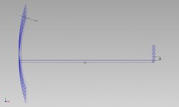
Lets put it into a graph:

Here I've drawn waves at a listening distance of 2.5 m, each driver gets a wave and the dotted lines behind the "blue wave" are 1.25" behind, meaning out of phase at 5400 Hz.
Where the continuous blue line touches the dotted line behind it is were a driver is out of phase with another driver. On our design axis, in line with the bottom diver, we see that none of the other drivers is completely out of phase with another driver. This is the worst case scenario with this array at 5400 Hz, be it, at a distance of 2.5 meter.
(they are actually within a quarter wave distance, and still summing positively, directly in line with the bottom driver)
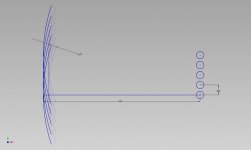
Let's examine closer to the array:

See how at 1 meter distance the situation has changed? The upper most driver's wave front is out of phase with the bottom driver (check it's dotted line) at our design axis.
The rest of them still sum.
This shows that driver spacing does have an influence on the resulting combing. But not like you claimed it would. If I had more drivers in between the top and bottom one, thus spaced closer together, the top driver would still be out of phase with the bottom one at 1M distance. However the transition would be more smoothed out due to having multiple drivers sum and subtract. Getting closer in behaviour to a continuous array.
But not in any way like you said it would, concluded from that center to center spacing.
At 2.5 meter none of the drivers would be out of phase with another on our design axis at 5400 Hz. This does not depend on the number of drivers in our short array here. It is determined by the distance from the array and the length of the array. More drivers packed closer together would fill in the spots in between, kind of like anti-aliasing. Getting you closer to a seamless array. Now make it floor to ceiling and assume the floor and ceiling are reflective.
Still, my argument holds up. You can't name a frequency and state it will start combing at that frequency based on center to center driver distance. As we'd need to know the distance from the array as well as it's length.
Lets put it into a graph:
Here I've drawn waves at a listening distance of 2.5 m, each driver gets a wave and the dotted lines behind the "blue wave" are 1.25" behind, meaning out of phase at 5400 Hz.
Where the continuous blue line touches the dotted line behind it is were a driver is out of phase with another driver. On our design axis, in line with the bottom diver, we see that none of the other drivers is completely out of phase with another driver. This is the worst case scenario with this array at 5400 Hz, be it, at a distance of 2.5 meter.
(they are actually within a quarter wave distance, and still summing positively, directly in line with the bottom driver)
Let's examine closer to the array:
See how at 1 meter distance the situation has changed? The upper most driver's wave front is out of phase with the bottom driver (check it's dotted line) at our design axis.
The rest of them still sum.
This shows that driver spacing does have an influence on the resulting combing. But not like you claimed it would. If I had more drivers in between the top and bottom one, thus spaced closer together, the top driver would still be out of phase with the bottom one at 1M distance. However the transition would be more smoothed out due to having multiple drivers sum and subtract. Getting closer in behaviour to a continuous array.
But not in any way like you said it would, concluded from that center to center spacing.
At 2.5 meter none of the drivers would be out of phase with another on our design axis at 5400 Hz. This does not depend on the number of drivers in our short array here. It is determined by the distance from the array and the length of the array. More drivers packed closer together would fill in the spots in between, kind of like anti-aliasing. Getting you closer to a seamless array. Now make it floor to ceiling and assume the floor and ceiling are reflective.
Attachments
In my "CBTish" design, the primary innovation is that all of the drivers in the array are playing full-tilt at low frequencies. IE, in the Keele CBT, at 200Hz the drivers at the edge of the array are getting less than 10% of the power than the drivers at the center are. In my "CBTish" design, every single driver is giving 100% at 200Hz.
But according to your schematic, at low frequencies you have 1 driver going full tilt, and 4 drivers going half tilt. At higher frequencies, those 4 drivers go even less than half tilt. There's a contradiction between your words and your schematic... I'm not sure which one best represents the ideas you are having.
Also, the JBL design already has all the drivers playing together at low frequencies (at least according to the schematic and patent... not positive if they implemented it that way in the commercial products). In fact, if my understanding of the patent is correct (haven't looked at it in over a year) they can make an array that barely brings down the magnitude response of the outer drivers at high frequencies. Because they see such a high order crossover, there's substantial phase delay at frequencies well below the crossover frequency. In effect, the passive components are there more for phase delay than magnitude reduction. From a power handling / SPL standpoint, they did a good job.
Last edited:
I have always wanted to build a line array and am intrigued. From what I understand a relatively flat power response and clean impulse response is what we are looking for in a great speaker system, and that is mostly why I have been experimenting with Unity and Synergy horns, besides they are just "cool".
I'm trying to ask "what do they sound like?" but knowing that I might be getting a subjective answer.
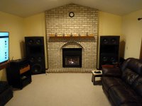
The last speakers I built have a "giant" sound that envelopes the listener from having pairs of woofers above and below the synergy horns and I am imagining that a floor to ceiling line array or CBT would have a similar quality?
Another advantage of the (multi) single driver line array seems to be no crossover near mid range frequencies, as a result a relatively linear phase, and would that not improve the power response through the mid region?
The other reason I am interested is line arrays would be ideal in my current listening room and would have a smaller footprint than these.
I'm trying to ask "what do they sound like?" but knowing that I might be getting a subjective answer.
The last speakers I built have a "giant" sound that envelopes the listener from having pairs of woofers above and below the synergy horns and I am imagining that a floor to ceiling line array or CBT would have a similar quality?
Another advantage of the (multi) single driver line array seems to be no crossover near mid range frequencies, as a result a relatively linear phase, and would that not improve the power response through the mid region?
The other reason I am interested is line arrays would be ideal in my current listening room and would have a smaller footprint than these.
Attachments
- Status
- Not open for further replies.
- Home
- Loudspeakers
- Multi-Way
- Cheaper CBTs