I cant help you there, while at 50 Hz I can still get more output than I'll ever need, lower than that my amplifier will run out of steam first before reaching the maximum the arrays can handle (though only slight).
I have plans to add subs. When I announced that, the people that have heard my arrays thought I was nuts, as they found the bass to be more than adequate.
I want to play with it, to learn. It will triple my volume displacement. I do not plan to simply cross over to subs at, say 60 Hz, I want to use the combination of arrays and subs to create more headroom. And, yes... I'd like to get a more powerful amplifier too for the arrays. Contrary to a lot of views if it matters or not, I will try to keep the group delay I have right now. Which can be seen in the wavelet I posted. Retaining minimum phase behaviour following the frequency curve throughout it's entire bandwidth is my goal. So the subs will add to, not replace the array output.
Werewolf
You might find the following analysis interesting.
Do the same infinite plane calculation that you did before, but now do it in rectangular coordinates instead of polar. You will find that the integrals look like two dimensional Fourier Transforms in x and y. Now consider that the volume velocity, or acceleration, is a function of x and y, but separable, a square or rectangular distribution rather than circular or elliptical. You will then see that the polar pattern generated (in k-space) is in fact the Fourier transform of this distribution.
If you simply use a Rect(x * a)*Rect(y * b) function you will find that the polar response is ( Sin(ka Sin( theta )) / (ka * Sin( theta )) )*( Sin(kb * Sin( phi )) / (kb sin( phi )) ). Where the angle theta is in x and phi is in y.
The exact same problem can be done in polar coordinates for a circle of radius a, but the transform will be the lessor known Bessel transform, however the result will be the well know polar response function J0( ka * sin(theta) ) / (ka * sin( theta ))
Last edited:
I cant help you there, while at 50 Hz I can still get more output than I'll ever need, lower than that my amplifier will run out of steam first before reaching the maximum the arrays can handle (though only slight).
I have plans to add subs. When I announced that, the people that have heard my arrays thought I was nuts, as they found the bass to be more than adequate.
I want to play with it, to learn. It will triple my volume displacement. I do not plan to simply cross over to subs at, say 60 Hz, I want to use the combination of arrays and subs to create more headroom. And, yes... I'd like to get a more powerful amplifier too for the arrays. Contrary to a lot of views if it matters or not, I will try to keep the group delay I have right now. Which can be seen in the wavelet I posted. Retaining minimum phase behaviour following the frequency curve throughout it's entire bandwidth is my goal. So the subs will add to, not replace the array output.
wondering how loud and how low you listen?
Its usually not a problem getting more than adequate SPLfor the audible bass range. Its getting enough SPL to feel that which is borderline too low to hear that requires the displacement
I would approach the comparison this way ...Consider a woofer with Sd= 300 sq.cm and Xmax= 12mm
and a floor to ceiling arrays of 25 3.5inch drivers with Sd= 36 sq.cm and Xmax=4mm.
Both the system has same air volume displacement capability.
Given the fact that SPL only decreases 3dB per doubling distance from a line source against 6dB for point source, an array obviously has advantages when it come to SPL at listening distance vs air displacement. This is very obvious at mid frequencies and up but never established for bass frequencies in a practical listening room situation and is difficult to test.
If the above mentioned systems generate 50Hz at same net air volume displacement and the listening position is 3m from the source, will the array have any SPL advantage?
I assume the nearfield to farfield transition point for the 10 inch woofer to be 0.5m from source ( I am just pulling this number out of nowhere) and that of the 2.3m high array to be 2.4m ( this is based on Griffin's paper on arrays ([f/1000]*[3H]^2)
so, we get an extra 1.9m nearfield transition after 0.5m from the source in case of the arrays. Hence the SPL advantage for same displacement at any listening distance greater than 2.4m from source is 10log(1.9/0.5) ~ 5.8dB.
So our array acts like a single woofer with Sd 300 sq.cm and 23.4mm Xmax???
*********
I have heard people say many times that in practical room listening situations spl decrease from woofer (point sources) per doubling listening distance is less than 6dB. So that brings them close to 3dB figure in case of an array. What they forget is that an array will get the same advantage if placed in the same room, hence SPL will decrease less than 3dB per doubling distance.
or Maybe not. Maybe an array deals differently with room gain ( not talking about vertical infinite line source extension here ). But that requires an answer or argument addressing that specifically, not something silly and simple as the above paragraph.
Hoping someone helps with this. Thanks 🙂
First, the line source : assume no walls, at first, but do assume a perfectly reflective floor and ceiling, for the floor-to-ceiling line array. The line array then becomes infinitely long, and the math in this thread is on-point ... especially since the CTC spacing will be much, MUCH shorter than the wavelength of 50Hz (22 feet).
Now, the point source : also assume no walls, at first, but also do assume a perfectly reflective floor and ceiling, for the point source (for direct comparison to the line source). We can still use "image theory" of reflections to derive the response ... we still have an infinite sum of point sources, but this time they will be spaced by some non-zero distance (unlike the continuous sum of point sources, with zero spacing, for the continuous line source). The CTC spacing of these sources becomes quite comparable to the wavelength of 50Hz. I'm sure the math has been done (maybe someone presented in this thread already?) ... it's a single, discrete, but infinite summation of point source responses. I'll give it some thought.
At this point, we'd have a direct comparison ... for any frequency ... between a floor-to-ceiling line array and a point source between that same floor and ceiling. Maybe see what we learn, and think about adding walls ...
wondering how loud and how low you listen?
Its usually not a problem getting more than adequate SPLfor the audible bass range. Its getting enough SPL to feel that which is borderline too low to hear that requires the displacement
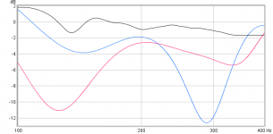
Fair view about the feel thing but have a hunch about what most listen to at listening position including myself have huge bounce problems in 100-400Hz area and having that area better than most think makes a big difference to the feel thing, what i mean is visualized below in blue trace is floor bouncing problem (>-10dB) when a single point speaker is positioned on a pedestal 45cm above floor and red trace is when its positioned 90cm aboved floor, then compare to black trace which is what wesayso actual share for his listening position.
Attachments
wondering how loud and how low you listen?
Its usually not a problem getting more than adequate SPLfor the audible bass range. Its getting enough SPL to feel that which is borderline too low to hear that requires the displacement
I've shown the curve in which you can see how low, noting that music seldom has high energy notes down that low.
The level I usually listen to, as measured with a RadioShack SPL meter is ~85 to 87 dB on average. For Home Theatre I lower that level to ~80 dB to keep it sane.
I've encountered one song that needed a gain structure change for me. That was: A Perfect Circle - Lullaby. This song does have high energy notes at about 25 Hz. (felt as a pressure build up, more than heard)
An externally hosted image should be here but it was not working when we last tested it.
Hardest hitting notes are at ~32 Hz, but the pumping bass at 25 Hz is just a few dB behind. That last part is felt more than heard.
Most songs roll off in energy below 40 Hz. The above song is an exception. Even JRiver's track analysis misses that bottom energy to get a sane playback level. The build-up of that pumping bass is fun though. Play at your own risk. 🙂
Disclaimer: Sorry, I have never listened to that classical piece with the cannons... 🙂 Just not my thing.
P.S. That RadioShack SPL meter never is far away. I want to preserve my hearing as it is easy to up the level without stressing the arrays. It gets louder but you don't really notice it. Until you try to talk to someone. That's why I analyse every song within JRiver to have it play at an equally loud level no matter the dynamic range present in the song.
Last edited:
@BRYTT - Ha! Still working on my own bounce problem but its up around 430 Hz and so doesn't affect "feel". Line array is where I might end up if all else fails but going to try taller horns first.
Hoping this thread will address shorter arrays and combing issue quantitatively.
@Wesayso - I don't listen any louder than you but I still feel need for more bass than a single 15" woofer per side can supply. I like to feel the low bass but around 30 Hz I lose corner support due to walls becoming transparent and come up short.
Interesting comparison between 3-way and full range line array bass is with regard to modulation distortion My woofers play up to 300 Hz and have an Xmax of 14 mm. Your TC9s move less than 2.5 mm but play up to 20 Khz. Klipsch's analysis showed that modulation distortion is proportional to both excursion and the maximum frequency played. I think we both benefit from moving the lowest octave or two to separate subwoofers. I've got two in the garage waiting for a warm day for me to finish applying the veneer.
@nc535 didn't your original plans include woofers on top as well as below the horns? 🙂
Your volume displacement is much more than what I have. Too bad it doesn't work out for the low end goal due to the walls. I've often mentioned liking the idea of a Synergy horn (with low end capabilities like bushmeister's example) within an (floor to ceiling) array of woofers for the low end, the Synergy being part of that array.
Your volume displacement is much more than what I have. Too bad it doesn't work out for the low end goal due to the walls. I've often mentioned liking the idea of a Synergy horn (with low end capabilities like bushmeister's example) within an (floor to ceiling) array of woofers for the low end, the Synergy being part of that array.
@nc535 didn't your original plans include woofers on top as well as below the horns? 🙂
Your volume displacement is much more than what I have. Too bad it doesn't work out for the low end goal due to the walls. I've often mentioned liking the idea of a Synergy horn (with low end capabilities like bushmeister's example) within an (floor to ceiling) array of woofers for the low end, the Synergy being part of that array.
Yes, initially I planned woofers on top as well as on bottom but I found the height intimidating, given the weight of the bass bin, and then used the intended upper woofer's space for bass traps. That is why I have two woofers on hand to use as subs. I think/hope separate subs used <60Hz will be solution for both room modes and modulation distortion..
re' Bushmeister example
A small synergy embedded in a line would solve the lobing and HF beaming issues with discrete line arrays whereas a big embedded Synergy might be "un-aesthetic". How do you integrate line array bass with point source mid+treble? Perhaps the woofer array can be weighted or frequency tapered so its attenuation with distance is point source.
@BRYTT - Ha! Still working on my own bounce problem but its up around 430 Hz and so doesn't affect "feel". Line array is where I might end up if all else fails but going to try taller horns first.
Hoping this thread will address shorter arrays and combing issue quantitatively...
Okay bounce problems are better than mine then because have several of them below 400Hz : )
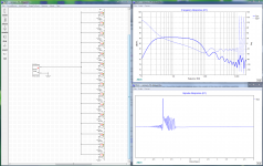
Xsim is not meant for this case but if we take the 15 distances wesayso share in post 237 think we can learn a bit about theoretical direct summing setting up 15 drivers, frd response curve per driver is based a Rephase 44,1kHz IR-file set as 20Hz-20kHz BW2 passband so phase is per 44,1kHz domain relative flat up high, first graph attached below is if all 15 drivers summed with same distance to listener and second one is with the various small delays set per driver. Think it tells say below 400Hz that because both amplitude and phase is not so far between the two models from that point on and lower in frq we should get theoretical good result.
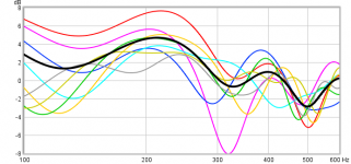
Myself is seriously thinking over try out a compromise array for 400Hz area and down, a compromise because its not covering floor all the way up to ceiling because i can't afford so many drivers and power amps but 8 times of relative small SB17NRXC35-8 should give me 1,5 meter high array and more than enough cone area and displacement than i need for that room so distortion numbers should theoretical get over average good. Here is overlaid individual curves for each woofer height position into 100-600Hz area exported from eight individual Jeff Bagby spreadsheets and think the black average trace show much less error than any of the individual height curves.
...@Wesayso - I don't listen any louder than you but I still feel need for more bass than a single 15" woofer per side can supply. I like to feel the low bass but around 30 Hz I lose corner support due to walls becoming transparent and come up short...
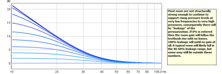
Ha ha probably it sound stupid but does it help close doors and windows especially below 30Hz, graph below is my room size set into Jeff bagby spreadsheet plotting only the room pressurization gain with room leakage set in steps of 10% including the build in spreadsheets guide for this field. Looks theoretical if one can break normal 40-60% numbers there is dB in sight especially at very lows but keep that door closed 🙂.
...Interesting comparison between 3-way and full range line array bass is with regard to modulation distortion My woofers play up to 300 Hz and have an Xmax of 14 mm. Your TC9s move less than 2.5 mm but play up to 20 Khz. Klipsch's analysis showed that modulation distortion is proportional to both excursion and the maximum frequency played. I think we both benefit from moving the lowest octave or two to separate subwoofers. I've got two in the garage waiting for a warm day for me to finish applying the veneer.
Good points there but will say for wesayso's case that myself didn't physical see any of the 50 TC9s make visible movement in normal role as a music system, another case for maxed out frequency domain is headphones and think they also can go relative far in quality.
Attachments

Last edited:
@BRYTT
Yes I have woofer on floor serving 300 Hz and down so obviously no floor bounce. Mine is a corner horn so no boundary interference. Its a more complex situation with conventional speakers out in the room
But an elevated point source will have floor and ceiling bounce which leads to large horn or array or some combination. If doing that, one needs to switch from horn to array while horn still has pattern control. Assuming you get that right, then you have controlled directivity in the horn region and uncontrolled directivity below, which isn't good for power response, unless the horn is 90H and in a corner.
Clever to use XSIM to see combing. I will have to figure out how to do that. What driver spacing were you modelling? Can you change the observation point correspondence from seated to standing equivalent?
Look at SpeakerDave's classic line array paper. The original version has simplified formula for summing spaced point sources that one could build a spreadsheet or program around.
Unfortunately my room has no doors to close. I hoped for room gain when I designed the speakers but it didn't materialize. Recall what Dr. Geddes has to say about room and corner gain.
APL has new extension to TDA (swept spaced tones and fixed low tone with sweeping send tone) that shows IM you might want to try out, even with cone movement so mall in the array. The IM effect of cone movement is proportional to frequency; IM might be there even if you can't see the movement.
Looks math skills is requested over here http://www.diyaudio.com/forums/software-tools/317811-xsim-3d-development-math-help.html#post5317462 cause creator of XSim bwaslo try to incorporate 3D stuff as driver positioning and room boundary effects into program, here a quote looking good from over there ... 🙂

so far, so good, I get reasonable looking results for things like line arrays and D'Appolito configurations
It is well known in the theory of waves that the impulse response has a tail in all odd dimensions and none in the even ones...
Do you have a reference for this?
I have had a think about the infinite line source and there still seems some inconsistency.
Is it not possible to create a cylindrical impulse wave front?
It's the same 3-dimensional air that supports non-dispersive wave front of spherical or flat shape.
And a cylindrical wave front transforms seamlessly into a plane wave front as the radius increases.
So the physics should be essentially identical.
I am not sure that there is not some confusion of the dimensionality of the co-ordinate system with that of the physics of the wave.
Funnily, since you mentioned gravitational waves, there was some kind of similar problem in the early days of GR.
Best wishes
David
i'm still wading through this complex math to see if i can gain an understanding of how it works in real time with the frequency and amplitude shifting as that seems to be what most array correction is about so that phase effects /comb filtering is negligible/acceptable.
is it correct to assume light and sound behave the same just because both are considered waves?
is it correct to assume light and sound behave the same just because both are considered waves?
A few things to remember ...i'm still wading through this complex math to see if i can gain an understanding of how it works in real time with the frequency and amplitude shifting as that seems to be what most array correction is about so that phase effects /comb filtering is negligible/acceptable.
is it correct to assume light and sound behave the same just because both are considered waves?
- For an Infinite Line Source (for kr significantly greater than unity), the magnitude response falls at 3dB per octave, also 3dB per doubling distance. The phase response has 2 components: a constant phase shift of 45 degrees, plus a linear phase shift corresponding to the distance from the line. These statements INCLUDE: all comb filtering effects, all magnitude and all phase effects. ALL of the tiny little elements that make-up the infinite line have been calculated and included, in magnitude, in phase, and in time ... in any & all ways you want to consider 🙂
- YES, when it comes time to build a floor-to-ceiling approximation of an "infinite" line, one must consider the center-to-center spacing of drivers ... if the line is made of discrete drivers, that is, rather than a tall ribbon (for example) ... to comprehend, or minimize, the interference effects of discrete drivers placed a few inches apart.
i have to take your word for it as i fail to understand where and how this is accounted for in the math (i'm still working towards a better math to english translation that i can understand)
for the moment i'll just follow along!
for the moment i'll just follow along!
i have to take your word for it as i fail to understand where and how this is accounted for in the math (i'm still working towards a better math to english translation that i can understand)
for the moment i'll just follow along!
I know you're stuck on the idea that there "must" be comb filtering effects, from all of the several "point sources" that constitute a continuous, infinite line ... and somehow, we're just "ignoring" it 🙁
Maybe think of it this way, and use your favorite modelling software to help ...
We don't have a few drivers, or point-sources, spaced a few inches apart, in the continuous infinite line. We a have TRILLION of them, spaced ONE MILLIONTH OF AN INCH APART. No wait ... we have a hundred times that many, spaced much, MUCH closer! Where is the first comb-filtering "null", in frequency, with point sources spaced by one millionth of an inch?
Only my graduate class in Advanced Engineering Mathematics, which had no book, only professors notes. We have seen that its true for 1 through 3, four is TBD (werewolf's working on that one I'm sure!🙂)Do you have a reference for this?
Of course, the fact that the impulse response in 2D has a tail does not preclude a cylindrical wave front, given the proper source velocity.I have had a think about the infinite line source and there still seems some inconsistency.
Is it not possible to create a cylindrical impulse wave front?
Best wishes
David
I believe that the infinite cylinder results are so non-intuitive because there is no such thing in real life. So we simply don;t have any intuition from experience. As I have said, the results for a finite cylinder are very much like what we are used to seeing in 3 dimensions.
Of course, the fact that the impulse response in 2D has a tail does not preclude a cylindrical wave front, given the proper source velocity.
Does it have a tail when approximated by mirroring off of ceiling and floor boundaries? Don't see why it would, but maybe I'm just not seeing it.
Yes, the infinite line source "created" by using a floor/ceiling reflections from a finite line will have the same impulse response as the infinite line. It will also have the same frequency response as the infinite line (if the impulse responses are identical, so are the frequency responses ... and vice versa). The "image theory of reflections" is accurate for all domains: space, frequency (magnitude and phase) and time.Does it have a tail when approximated by mirroring off of ceiling and floor boundaries? Don't see why it would, but maybe I'm just not seeing it.
Last edited:
- Home
- Loudspeakers
- Multi-Way
- Infinite Line Source: analysis