Transistor models can be a tough thing these days, partly because of changes that may have resulted from some mergers among semiconductor manufacturers. Even with manufacturers, they have likely tried to retire some of the older processes and consolidate processes. Given that transistor datasheet specs are often pretty loose, if they choose, they can fit new versions of an older transistor into the spec windows of their original versions. If they do that, they will likely not do new plots of the typical characteristics that are most helpful to us in the absence of doing our own measurements.
Lately I have spent some time looking at ways of determining VAF numbers in the lab using ac measurements to find essentially small-signal VAF numbers at different operating points for a given small-signal transistor. I've had some success, but more verification of my results needs to be done, perhaps with two different small-signal measurement techniques for a sanity check. In doing those measurements, I also wanted to see how much VAF was a function of operating point voltage and current, to get a better idea of nonlinearity in the Early effect.
Finally, as we have often been taught, especially in the linear IC design business, we want to design circuits that are inherently less sensitive to transistor parameters to the extent possible. Since Early effect is largely seen as an effect on transistor current gain, circuits that are less dependent for their performance on transistor beta are a good way to go.
Cheers,
Bob
These are all very valid points, especially the last reminder. Thank you for making this new effort.
During thinking about parameters, I came across a BC55x datasheet from CDIL, see attachment. They really provide maximum output admittances for the different gain groups. If I read the figures right, with around 10kOhms output resistance for group "C" at 5V and 2mA, this would result in an Early voltage of 15V as minimum value, if one simply transforms AC into DC specification as first approximation.
Even if this is a low figure, one should not say that all is becoming worse these days ;-)
Matthias
Attachments
Last edited:
I noticed that CDIL calls 'hRE' the 'voltage feedback ratio'. Another argument for 'emitter follower has 100% feedback'😉
Jan
Jan
Transistor models can be a tough thing, we want to design circuits that are inherently less sensitive to transistor parameters to the extent possible. Since Early effect is largely seen as an effect on transistor current gain, circuits that are less dependent for their performance on transistor beta are a good way to go.
Cheers,
Bob
Exactly right.
And as far as I remember we designed very good Audio Amps a long time before the Spice models. We had to calculate it the old way.
Also bear in mind that some very good Amps has been simulated and designed with the "original" Spice models (not the Cordell Models) and the Amps works perfectly well.
All the best
Reodor
🙂 😎
Just about anything you could possibly want to measure or know about a transistor can be learned from a good curve tracer. Tektronix, back when they were producing the 576 etc produced a booklet series on measuring device characteristics. The most comprehensive I have seen.
I used to own a 576 but now own a Chinese version (more compact, lighter wgt, SS) which allows me to view the characteristic curve of 2 devices at the same time..... great for matching.
Best thing for learning what a device is all about and what it can do..... no guess work from incomplete/inaccurate data sheets etc.
THx-RNMarsh
Last edited:
Everything except capacitance parameters, noise parameters, temperature parameters, transition frequency ("fT"), and ... (I'm sure others will add to the list).
Both the Early voltage effect, and beta, depend on the doping level in the base. Gummel showed that the transistor collector current was dependent on the total doping in the base, which leads to the "Gummel number" and the basic SPICE parameter Isat.
The Early voltage is dependent on the spread of the collector-base depletion region into the base. So for a higher transistor gain, that implies lower doping, and that means that not only does the depletion region spread further into the base, but also takes up a bigger percentage of the base doping as it goes, hence the Early voltage is worse (lower) for the higher gain transistors.
The correlation between the gain and Early voltage is somewhat loose. Since the gain is more a function of the total doping, it is less sensitive to how the doping is distributed. On the other hand, the Early voltage is dependent on how the doping level changes right next to the collector, hence more sensitive to local variations.
..and I have used my oscilloscope to set up transistor measurements for Early voltage, among other parameters...
Most of the curve tracer kits were boxes of parts which "set up transistor measurements" on an external oscilloscope. Here is the manual for one of the more famous examples: (link to .pdf)
Thanks, I enjoyed this HeathKit manual.Most of the curve tracer kits were boxes of parts which "set up transistor measurements" on an external oscilloscope. Here is the manual for one of the more famous examples: (link to .pdf)
Great memory, I regret loosing the manual of my Heathkit depth sounder, a clever little box handy on my boat.
Hi Mark,
The sad thing is, I have one of those around here somewhere. I think I know where it is. I'll have to pull it out and play with it sometime.
-Chris
The sad thing is, I have one of those around here somewhere. I think I know where it is. I'll have to pull it out and play with it sometime.
-Chris
Interesting link to the curve tracer kit.
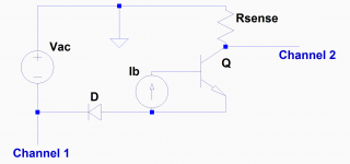
If it helps anyone I use an oscillator driving a power amp feeding a transformer load, that can be switched to feed into the primary or secondary winding to give a high current/low voltage measurement or high voltage/low current, a bridge rectifier on the output, then use a second (isolated, preferably) supply for the base current/gate voltage. Sweep the voltage from the oscillator control on the scope (dual channel, X-Y mode) measuring current through a 1 ohm resistor. One day I might get around to building a stepper for the base/gate drive and building it into a single unit.
If it helps anyone I use an oscillator driving a power amp feeding a transformer load, that can be switched to feed into the primary or secondary winding to give a high current/low voltage measurement or high voltage/low current, a bridge rectifier on the output, then use a second (isolated, preferably) supply for the base current/gate voltage. Sweep the voltage from the oscillator control on the scope (dual channel, X-Y mode) measuring current through a 1 ohm resistor. One day I might get around to building a stepper for the base/gate drive and building it into a single unit.
Thanks for that. Shouldn't this idea also work without a transformer, and for small-signal transistors without a power amplifier (depending on source voltage)?Interesting link to the curve tracer kit.
If it helps anyone I use an oscillator driving a power amp feeding a transformer load, that can be switched to feed into the primary or secondary winding to give a high current/low voltage measurement or high voltage/low current, a bridge rectifier on the output, then use a second (isolated, preferably) supply for the base current/gate voltage. Sweep the voltage from the oscillator control on the scope (dual channel, X-Y mode) measuring current through a 1 ohm resistor. One day I might get around to building a stepper for the base/gate drive and building it into a single unit.
Matthias
Attachments
Exactly right.
And as far as I remember we designed very good Audio Amps a long time before the Spice models. We had to calculate it the old way.
Also bear in mind that some very good Amps has been simulated and designed with the "original" Spice models (not the Cordell Models) and the Amps works perfectly well.
All the best
Reodor
You are right - many very high performance amps were designed without SPICE - including my MOSFET power amp with error correction. It is also true that simulating amplifiers even with crappy manufacturer's models is better than not simulating at all. In general, at the end of the day, simulating an amplifier with SPICE saves time in the lab, avoiding errors in design, and getting closer to the target design before even building the amp. It is also very helpful in uncovering borderline (or over-the-line) stability issues. Zeroing in on feedback compensation values is also helpful, especially if the models are decent. It is nice to have an amplifier that works first crack out of the box and only needs tweaking and refinement in the lab.
If SPICE does not quite get the distortion right, that's not a big deal. However, it does set reasonable expectations, which, if way off, may indicate a build error, a parasitic oscillation, or a significant real-world source of distortion, such as distortion from magnetic coupling of nonlinear output stage currents into the signal path. If SPICE is way off, you need to look harder to find out if it is one of these kinds of things and not just optimistic simulation results.
Cheers,
Bob
Again a nice trick "for the kitchen table". Thanks!I use a transformer to provide a floating output. This is to allow the scope channels to be grounded, and the bias supply (which is not floating) to be referenced to ground too, and then the current sense resistor voltage can float accordingly.
Matthias
Hi All. I would just like to clarify something that I was re-reading in Bob's book. On page 15 it talks about transconductance and provides the formula gm = delta Ic / delta Vbe. All that makes perfect sense to me.
In another section on transconductance I would like some clarification on a section on page 18 under the paragraph heading Transconductance.
Towards the end of that paragraph it says "The slope of the curve increases as Ic increases; this means that the transconductance also increases. Transconductance is given simply as gm = Ic / Vt where Vt = 26mV etc etc..."
I understand that the transconductance increases as Ic increases but Idon't understand the formula or how the formula relates to the slope of the line and the other formula gm = delta Ic / delta Vbe which makes perfect sense.
Can someone please provide me with an explanation.
Cheers...
I can't see how.It may be the context - 26mV Vbe is the delta that doubles Ic.
Jan
gm = Ic / Vt
and
gm = delta Ic / delta Vbe
can give you the same answer.
So I am assuming that somehow
gm = Ic / Vt is used to plot the slop of Ic so it can be used independent of the Value Vbe.
This is was the text seam to be saying. But I don't understand how.
I think that I am missing something...
Hi Bob,
I would appreciate if take a look and comment my compensation type I think that is in a way unique and novel.
www.diyaudio.com/forums/solid-state/317335-oitpc-output-inclusive-tpc-tmc.html
BR Damir
I would appreciate if take a look and comment my compensation type I think that is in a way unique and novel.
www.diyaudio.com/forums/solid-state/317335-oitpc-output-inclusive-tpc-tmc.html
BR Damir
Most of the curve tracer kits were boxes of parts which "set up transistor measurements" on an external oscilloscope. Here is the manual for one of the more famous examples: (link to .pdf)
I miss the Heathkits and their wonderful manuals. My first decent scope was a 15 MHz dual trace Heathkit.
Cheers,
Bob
- Home
- Amplifiers
- Solid State
- Bob Cordell's Power amplifier book