a search question
were can I find information ,design equations and schematics about the VLADIMIR CARVEAUX infra sound horn
please direct me to the appropriate site or thread
if possible mail the answer to my mail box: gonzaleshuerta24@gmail.com
thank you
jeovanny
were can I find information ,design equations and schematics about the VLADIMIR CARVEAUX infra sound horn
please direct me to the appropriate site or thread
if possible mail the answer to my mail box: gonzaleshuerta24@gmail.com
thank you
jeovanny
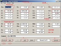
Получить чертёж с помощью HornResp,это легко!
Get the drawing by means of HornResp,this easy!
I have found the spreadsheet. But it has Old_calculation and New_calculation
The trick is that the new_calculation is dated 2007 and the old one -2009
Here are the pictures.
Does anybody know where is the new one or the right one?
Get the drawing by means of HornResp,this easy!
Attachments
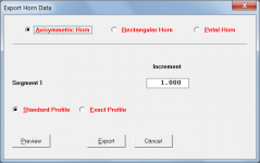
Get the drawing by means of HornResp,this easy!
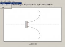
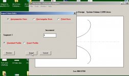
For axisymmetric Le Cléac'h horns, the Hornresp 'Standard Profile' option gives a result identical to the 'New Calculation' spreadsheets included in Jean-Michel's 2007 and 2009 Excel workbooks. There is no difference in the New Calculation results produced by the 2007 and 2009 spreadsheets, and while they provide a reasonably close approximation to the theoretically perfect profile, they are not an exact match.
The Hornresp 'Exact Profile' option exactly matches the theoretical ideal for an axisymmetric Le Cléac'h horn, and is therefore the suggested one to use.
See the following post for further background information.
http://www.diyaudio.com/forums/multi-way/140190-jean-michel-lecleach-horns-114.html#post2619419
Attachments
A new 1kHz tweeter horn. Horn expansion follows JMLC method,
The inner shape is similar to JBL 4367 waveguide.
more information :
HIFIDIY??-??????? - Powered by Discuz!=
The inner shape is similar to JBL 4367 waveguide.
more information :
HIFIDIY??-??????? - Powered by Discuz!=
Attachments

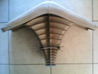
Thanks for that! I went to the other forum and read your posts. It took some reading and head scratching, but I finally saw what you are doing, and how. Nice way to build up a complex shape via layers. 
@ hsiehwm
Interesting
Be nice if you could post the details from the other thread, in here in English 🙂
Interesting
Be nice if you could post the details from the other thread, in here in English 🙂
Long thread (which I will read fully at a certain point ;-) ). Without opening a new thread, what is the right line of thought matching the best combination of cut-off frequency (Xo), JMLC horn choice (and why on that frequency) in combination with the TD-2001?
What are the extremes in this regarding side effects or limits in the low frequency region?
What are the extremes in this regarding side effects or limits in the low frequency region?
I would also look at what you will be using to cover below the 2001 and where you might need your crossover to be. Then make a LC horn with a flair rate around 1/2 your expected crossover frequency, aiming to have the mouth of the horn be a bit bigger than the LF driver (assuming a direct radiator). This will give you a good chance of matching the horizontal directivity between the two devices through the crossover region. Since the source sizes are about the same, you should have some frequency range to play with in choosing a crossover. You can consider driver linear and non-linear distortion and pick the best compromise.
For example, you use a 15" woofer for the midbass which you know starts to have problems above 800Hz. Then make a LC horn with ~400Hz flair rate which is about the same size as the 15" woofer.
For example, you use a 15" woofer for the midbass which you know starts to have problems above 800Hz. Then make a LC horn with ~400Hz flair rate which is about the same size as the 15" woofer.
I would also look at what you will be using to cover below the 2001 and where you might need your crossover to be. Then make a LC horn with a flair rate around 1/2 your expected crossover frequency, aiming to have the mouth of the horn be a bit bigger than the LF driver (assuming a direct radiator). This will give you a good chance of matching the horizontal directivity between the two devices through the crossover region. Since the source sizes are about the same, you should have some frequency range to play with in choosing a crossover. You can consider driver linear and non-linear distortion and pick the best compromise.
For example, you use a 15" woofer for the midbass which you know starts to have problems above 800Hz. Then make a LC horn with ~400Hz flair rate which is about the same size as the 15" woofer.
Aiming to get the TD2001 started as low as possible (500-800Hz), this would lead to either a JMLC350/400 or even a 600...right? Anyone with first hand experience and data on such TD2001 combinations?
I am Curious how the SPL curves would look having the TD-2001 on either a Tractrix-350 or a JMLC-600... anyone tried it and measured it?
- Horns by Auto-Tech
- Horns by Auto-Tech
Notes
1) The lower you set your c/o frequency the greater displacement limitation imposed on the output of the entire system given specific filter slopes.
2) When driver exit and horn entry slopes are matched, then [R] for a Tractrix horn is fixed. (for 0-Degrees of Freedom)
3) If a three-way system, why not divide frequency response into decade segments (approximately)?
WHG
1) If a three-way system, why not divide frequency response into decade segments (approximately)?
WHG
This has always been my approach: 1) <100 Hz multiple subs; 2) 100 - 1 kHz mid bass; 3) >1 kHz waveguide. It seems the most reasonable break points to me, although I do push the 1 kHz down if the designs directivity control can handle it.
Aiming to get the TD2001 started as low as possible (500-800Hz), this would lead to either a JMLC350/400 or even a 600...right? Anyone with first hand experience and data on such TD2001 combinations?
IIRC, the late JMLC prefers to XO the TD-2001 above ~1200Hz and with a high output impedance amp for best results.
I am Curious how the SPL curves would look having the TD-2001 on either a Tractrix-350 or a JMLC-600... anyone tried it and measured it?
- Horns by Auto-Tech
I used the Autotech JMLC-350 with TD2001 with Klipsch Jubilee clone folded horn as a 2 way system for years. As I recalled I was using a XO frequency of around 800Hz set via Electrovoice electronic crossovers. They sounded good but I eventually went up to the TD4001 with a new set of Autotech JMLC-350s with a larger throat size. My current crossover is around 650Hz using the LeCleach crossover recommendations.
No I did not have measurements with the TD2001. But I did make measurements using REW on the TD4001 based system. The response is remarkably flat using 1/6 Octave smoothing.
3) If a three-way system, why not divide frequency response into decade segments (approximately)?
WHG
I cross my mid-range driver at 600-6k Hz (one decade)...
Hello,
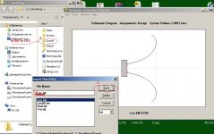
JMLC_quasi_elliptical.xls
There is a mistake, you should suppress the L19770 data and add the missing 0° data in the L19771

JMLC_quasi_elliptical.xls
There is a mistake, you should suppress the L19770 data and add the missing 0° data in the L19771

I am Curious how the SPL curves would look having the TD-2001 on either a Tractrix-350 or a JMLC-600... anyone tried it and measured it?
- Horns by Auto-Tech
Follow Eric's (EBA) posts for his system using 2001 and EJMLC600.
http://www.diyaudio.com/forums/multi-way/140190-jean-michel-lecleach-horns-144.html#post3416344
SMathews
JMLC_quasi_elliptical.xls
PS : for those who are about to make a tessellation, it will kill your script 😀
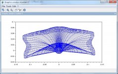
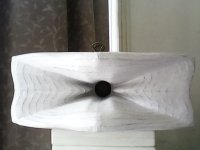
A new 1kHz tweeter horn. Horn expansion follows JMLC method,
The inner shape is similar to JBL 4367 waveguide.
more information :
HIFIDIY??-??????? - Powered by Discuz!=
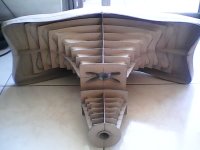
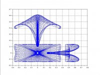
My new mid horn (1inch 320Hz), be calculated and built by the same method of my tweeter horn. In a rough listening comparison, it is more better than my old one at frequency extension.
Partisional expansion at throat section might be the major cause. This type cross-section has fewer higher_order_modes than simple circle or square with same area. In horn duct, tranverse wave propogation induce higher_order_modes. Like any resonance, higher_order_modes needs time to establish and decay. I think, heavier higher_order_modes not only affects horn directivity, but also dtsturbs sound phase.
Horn mesh data and building method in
HIFIDIY??-??????? - Powered by Discuz!
Attachments
Last edited:
Nice[FONT=Times New Roman, serif]My new mid horn (1inch 320Hz), [FONT=Times New Roman, serif]be calculated and built by the same method of my tweeter horn. [FONT=Times New Roman, serif]In a rough listening comparison, it is more better than my old one at frequency extension.[/FONT][/FONT][/FONT]
[FONT=Times New Roman, serif]Partisional expansion at throat section might be the major cause. [FONT=Times New Roman, serif]This type cross-section has fewer higher_order_modes than simple circle or square with same area. [FONT=Times New Roman, serif]In horn duct, tranverse wave propogation induce higher_order_modes. Like any resonance, higher_order_modes needs time to establish and decay. I think, heavier higher_order_modes not only affects horn directivity, but also dtsturbs sound phase.[/FONT][/FONT][/FONT]
[FONT=Times New Roman, serif]Horn mesh data and building method in[/FONT]
[FONT=Times New Roman, serif]http://bbs.hifidiy.net/thread-825216-8-2.html[/FONT]
Could you make a quick summary of the building method & materials in english, here ?
BR
Jean-Louis
- Home
- Loudspeakers
- Multi-Way
- Jean Michel on LeCleac'h horns