We can calculate the nonlinear base current due to Vaf to see if it matches the distortion figures.
Hi keantoken, thanks for contributing some analysis 🙂
Cordell's BC550C model tells me Vaf is 162 and from experience Hfe is about 500.
Your sums seem to assume that this figure of 500 is measured at 0 V Vce but this won't be the case. Anyway, accounting for the actual value of Vce for this measurement would only make a small difference to your calculations.
54.7nApp total error base current, which we can assume is mostly 2nd harmonic.
…
57uV error in 1V is 0.0057%. Most of this is still the fundamental though
(emphasis added by me). These two statements do not appear to be in agreement. What am I missing?
I'd like to fully agree. But if simulation work is rudely bashed by certain people around here, then one simply has to stay away.Hi keantoken, thanks for contributing some analysis 🙂
Have fun.
I'd like to fully agree. But if simulation work is rudely bashed by certain people around here, then one simply has to stay away.
Have fun.
I'm not sure if the earlier comments RE: simulation were being directed at you; certainly I didn't read it that way and thought they were just more general. I view the ability to use "ideal" components in simulation as one of simulation's most powerful benefits. So thank you for your contributions also.
Whilst I would have to agree that in the end, measurement (as long as it's been done properly) is reality, I also agree with Bob that if simulation and measurement disagree to a very large extent, further investigation is required and it is possible that the error lies in the measurement method (this final comment is meant as a general one rather than aimed at anything specific being currently discussed).
Last edited:
BF862 is also EOL. Anything replacing that ?
Why did your link disappear? Thanks for the article; I've only read about a page so far but it's well written, and looks really useful and relevant to the discussion at hand.
🙂 The link was removed by me because I found PB2 on the previous page had already posted it ! I couldn't delete my entire post so I asked about the BF862. Do we have an alternative ?....apart from the the LSK series .
I wonder if "Distortion in low-noise amplifiers" by Eric F. Taylor, Wireless World August, 1977
might shed any light on the input current distortion question. We've discussed the article back in
2005 but I've not looked at the article since then. I remember that someone had it in .pdf format.
Found it in .pdf format, in case there is interest: http://www.keith-snook.info/wireles...d-1977/Distortion in low-noise amplifiers.pdf
It seems that the article was taken down, it is still in the index here but the
link no longer works: ~ Scanned and cleaned up Wireless World Articles ~

uh. I found neutralization on input pair to help, also. Sometimes easier and/or cheaper than cascoding ips.
Just sayin'
THx-RNMarsh
What is neutralization?
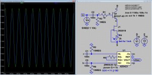
So (I thought) go measure (build something on the realty plane 🙂).
But... new hurdles pop-up, anyone? what is this difference between I(R1) and Ib(Q1)?
O.k. I see it, I'm an idiot 😕 sorry, 100kOhm was to small an resistor 😀
Attachments
It seems that the article was taken down, it is still in the index here but the
link no longer works: ~ Scanned and cleaned up Wireless World Articles ~
That I can solve:
Goto Internet Archive: Wayback Machine
Enter the URL
Select a date (I used early 2014)
Open the PDF
Worked for me 🙂
O.k. I see it, I'm an idiot 😕 sorry, 100kOhm was to small an resistor 😀
I still don't get it, Why would I(R1)!=I(bQ1) at any R1 value?
Jan
We can calculate the nonlinear base current due to Vaf to see if it matches the distortion figures. [snip]
Nice thinking!
Jan
O.k. I see it, I'm an idiot 😕 sorry, 100kOhm was to small an resistor 😀
The 8421 has ultra-low bias current. You might be better to do away with the input network and just connect the inputs direct across R1. What is the DC level of the Q1 base to ground?
That I can solve:
Goto Internet Archive: Wayback Machine
Enter the URL
Select a date (I used early 2014)
Open the PDF
Worked for me 🙂
The normal link works for me!
I still don't get it, Why would I(R1)!=I(bQ1) at any R1 value?
Jan
Took a while for me to spot it too! Current in C1, R2, C3, R6 (input network to current-measuring in-amp).
I still don't get it, Why would I(R1)!=I(bQ1) at any R1 value?
Jan
R2 and R6 at 100k are to low a value, the 10MEG's solve it 🙂
The normal link works for me!
The normal link did not work for me, the solution did, as it will do for the OP
The 8421 has ultra-low bias current. You might be better to do away with the input network and just connect the inputs direct across R1. What is the DC level of the Q1 base to ground?
I will do that, the network was there as some kind of a safety and to make other measurements possible (and it removes the DC component of Ib).
- Home
- Amplifiers
- Solid State
- Bob Cordell's Power amplifier book