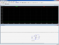
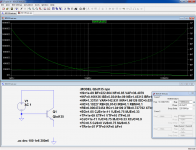
Here is an illustration of why sims and spice models should always be taken with a pinch of salt (or spice!):
The circuit couldn't be simpler: a transistor operating in saturation.
But this transistor (BSS63) is no mean, ordinary one: it is a super-transistor made by Siemens.
It is so good that its C-E saturation voltage is low, very low, so low in fact that it becomes negative: as you can see, its collector output is 60mV higher than the 1V source..
It thus acts as a completely static DC stepup converter, drawing the additional energy out of thin air.
If you stack 60 such circuits, you will double the input voltage, and get 50% of the energy for free.
Bravo Siemens!
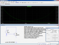
Other transistors, all from Siemens also exhibit this quirk.
Have fun!
The circuit couldn't be simpler: a transistor operating in saturation.
But this transistor (BSS63) is no mean, ordinary one: it is a super-transistor made by Siemens.
It is so good that its C-E saturation voltage is low, very low, so low in fact that it becomes negative: as you can see, its collector output is 60mV higher than the 1V source..
It thus acts as a completely static DC stepup converter, drawing the additional energy out of thin air.
If you stack 60 such circuits, you will double the input voltage, and get 50% of the energy for free.
Bravo Siemens!
Other transistors, all from Siemens also exhibit this quirk.
Have fun!
Attachments
Hi Elvee,
it is a bit inconsistent that Siemens partly will withdraw from energy equipment business if they are capable of allowing such nice things.
Kind regards,
Matthias
PS. In another thread, I do not get reply to the following question: Are the old, but still quite nice BD139/40 from different manufacturers, e.g. STM and Onsemi /Fairchild, comparable? All I know is that the older Philips version is definitely a different (faster) device.
Do you know something about that?
Background: Are Bob Cordell's models valid for the STM devices?
Last edited:
The old BD's from Philips and Telefunken were indeed faster than the others, but each variety has its own flavor.
I must have a good number of samples in stock, I'll try to compare their Ft's
I must have a good number of samples in stock, I'll try to compare their Ft's
Hi Elvee,
Kind regards,
Matthias
This would be great. They fit that well as drivers in a low to medium power amp, at least in simulation ...The old BD's from Philips and Telefunken were indeed faster than the others, but each variety has its own flavor.
I must have a good number of samples in stock, I'll try to compare their Ft's
Kind regards,
Matthias
STM now provides models
Hi Elvee,
I only recently have started to sim and solder again. Some years ago, STM did not provide models on the Web. Therefore, my question.
Now, they have one. Just simmed their model BD139 @ 10V @ 100mA.
Result: Ft around 50MHz. Bob's model, presumably derived from Onsemi, gives Ft around 150MHz.
So, they state that their device is slower. I do not assume that the devices are in fact better than the model suggests. Quite probably, KSC2690 will also fit in the design.
Thanks and kind regards,
Matthias
Here are some results. I had fewer different samples than I thought initially.
Measurement conditions are: Vce=5V, F=35MHz, Ic=100mA. I also measured Ccb@0V.
BD139 Philips: 175MHz, 32pF
BD131 Philips: 110MHz, 120pF
BD135 ONsemi: 120MHz, 33pF
BD135 Telefunken: 160MHz, 32pF
BD139-10 Siemens: 88MHz, 32pF
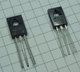
BD137 ?? probably Toshiba, see pic: 35MHz, 38pF
Vce=5V, F=30MHz, Ic=100mA
BD140 Philips: 150MHz, 50pF
BD140 Telefunken: 135MHz, 61pF
BD140 ST: 120MHz, 100pF
BD140 ??? see pic: 45MHz, 35pF
The BD137 and 140 of unsure origin are almost certainly from an Asian manufacturer. The BD137 case style looks very much like Toshiba, and the BD140 has a logo, but I don't recognize it, maybe someone can?
Measurement conditions are: Vce=5V, F=35MHz, Ic=100mA. I also measured Ccb@0V.
BD139 Philips: 175MHz, 32pF
BD131 Philips: 110MHz, 120pF
BD135 ONsemi: 120MHz, 33pF
BD135 Telefunken: 160MHz, 32pF
BD139-10 Siemens: 88MHz, 32pF
BD137 ?? probably Toshiba, see pic: 35MHz, 38pF
Vce=5V, F=30MHz, Ic=100mA
BD140 Philips: 150MHz, 50pF
BD140 Telefunken: 135MHz, 61pF
BD140 ST: 120MHz, 100pF
BD140 ??? see pic: 45MHz, 35pF
The BD137 and 140 of unsure origin are almost certainly from an Asian manufacturer. The BD137 case style looks very much like Toshiba, and the BD140 has a logo, but I don't recognize it, maybe someone can?
Attachments
how did you Ft measurements?
Please show us your test setup.
I worked in Philips Semiconductor Plant in Brazil in 80's(It was called IBRAPE) and the production test was done with an very interesting automatic machine controlled with PDP11 16 bits computer in that time.
Please show us your test setup.
I worked in Philips Semiconductor Plant in Brazil in 80's(It was called IBRAPE) and the production test was done with an very interesting automatic machine controlled with PDP11 16 bits computer in that time.
Hi Elvee,
It's probably difficult to state that, e.g., the ST devices were inferior (save the high Ccb). Will make a short BD140 sim with their modell, tomorrow.
I'm wondering about the fluctuations over the same transistor type from one manufacturer. If I remember right, the datasheets specify, if any, only a typical Ft.
Without performing new measurements: can anybody comment on that problem in general?
Altogether, I will probably try to use the KSC2690 combo.
Thanks again for the effort!
Kind regards,
Matthias
thanks for these results!Here are some results. I had fewer different samples than I thought initially ...
It's probably difficult to state that, e.g., the ST devices were inferior (save the high Ccb). Will make a short BD140 sim with their modell, tomorrow.
I'm wondering about the fluctuations over the same transistor type from one manufacturer. If I remember right, the datasheets specify, if any, only a typical Ft.
Without performing new measurements: can anybody comment on that problem in general?
Altogether, I will probably try to use the KSC2690 combo.
Thanks again for the effort!
Kind regards,
Matthias
Hi Elvee,
tried to simulate BD135-ON and BD140-ST with their current models.
For the ST device, I removed the subcircuit envelope in the model, thus ignoring the microhm lead resistances.
For Ft, I looked at the 0dB point of collector current in the simple circuit below. For Cbc, I switched to .OP analysis and went into the SPICE log.
BD135-ON: Ft=90Meg, Cbc=4.8p
BD140-ST: Ft=1.8G, Cbc=0.26p
BD139-CO: Ft=130Meg, Cbc=11p (Bob Cordell's model)
BD140 result from ST model is just one league below your example from post #1. When looking at Cbc, Bob's result compares best to the ONsemi datasheet.
Hopefully, I did measure the right thing.
What do your quite large Cbc values mean? Are they really the same thing as depicted as Cob in the ONsemi BD135 datasheet diagramm?
Kind regards,
Matthias
Here are some results. I had fewer different samples than I thought initially ...
tried to simulate BD135-ON and BD140-ST with their current models.
For the ST device, I removed the subcircuit envelope in the model, thus ignoring the microhm lead resistances.
For Ft, I looked at the 0dB point of collector current in the simple circuit below. For Cbc, I switched to .OP analysis and went into the SPICE log.
BD135-ON: Ft=90Meg, Cbc=4.8p
BD140-ST: Ft=1.8G, Cbc=0.26p
BD139-CO: Ft=130Meg, Cbc=11p (Bob Cordell's model)
BD140 result from ST model is just one league below your example from post #1. When looking at Cbc, Bob's result compares best to the ONsemi datasheet.
Hopefully, I did measure the right thing.
What do your quite large Cbc values mean? Are they really the same thing as depicted as Cob in the ONsemi BD135 datasheet diagramm?
Kind regards,
Matthias
Attachments

These are the models downloaded today from their Web sites.Are the results from simulation of models on LTspice, or from real devices?
...But this transistor (BSS63) is no mean, ordinary one: it is a super-transistor made by Siemens.
...It thus acts as a completely static DC stepup converter...
Have you looked at the model to see what they have done to cause this problem?
It's not even clear to me how to do this, just a minus value for a parameter?
Best wishes
David
I think it is a well known fact that Spice doesn't take care of the saturation behavior of BJTs.
I think these results are no good for the generic pnp and npn generic as well as any model.
I think these results are no good for the generic pnp and npn generic as well as any model.
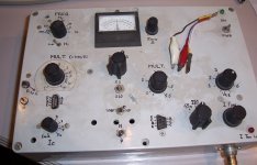
I am afraid it is neither automatic, nor computer controlled, it is a purely manual affair, and completely DIY, for both the design and the construction:how did you Ft measurements?
Please show us your test setup.
I worked in Philips Semiconductor Plant in Brazil in 80's(It was called IBRAPE) and the production test was done with an very interesting automatic machine controlled with PDP11 16 bits computer in that time.
There are in fact two instruments in the same box: on the right is the "general purpose" section, with Vce settable from 0 to 7V and Ic from 0 to 1A.
It requires an external RF generator to supply the measurement frequency.
The maximum frequency is 30~40MHz and the extrapolation ratio is ~6 maximum, leading to a maximum measured Ft of 200 to 250MHz.
If used for comparisons only, it can go somewhat higher.
The left part is simplified, with only Ic adjustable from 1 to 10mA, and has its built-in generator.
The generator reaches 100MHz, and the extrapolation ratio reaches 16, meaning it is possible to measure small-signal transistors up to ~1.5GHz.
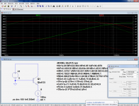
Here is how I measure the parameters in spice: the hardware methods are conceptually identical.Hi Elvee,
tried to simulate BD135-ON and BD140-ST with their current models.
For the ST device, I removed the subcircuit envelope in the model, thus ignoring the microhm lead resistances.
For Ft, I looked at the 0dB point of collector current in the simple circuit below. For Cbc, I switched to .OP analysis and went into the SPICE log.
BD135-ON: Ft=90Meg, Cbc=4.8p
BD140-ST: Ft=1.8G, Cbc=0.26p
BD139-CO: Ft=130Meg, Cbc=11p (Bob Cordell's model)
BD140 result from ST model is just one league below your example from post #1. When looking at Cbc, Bob's result compares best to the ONsemi datasheet.
Hopefully, I did measure the right thing.
What do your quite large Cbc values mean? Are they really the same thing as depicted as Cob in the ONsemi BD135 datasheet diagramm?
For the Ft, I inject a modulation in the emitter current and look for the intercept of the base and collector current magnitudes: about 85MHz in the case of the Onsemi:
For the Ccb the magnitude of the collector to base impedance is ~1.59kΩ (and the phase is close to -90°, which means we measure the right thing).
This translates into 10pF, very optimistic compared to the physical measurement made in exactly the same way.
Note that the bias is also 0V.
If a DC bias is added, the capacitance decreases, logically:
With 5V, it is halved:
If the physical BD135 is measured @2.5V DC, the capacitance drops to 22pF.
Note that this measurement does not exactly yield Ccb, because the emitter is left open (unguarded), which will add a little less than the collector to emitter capacitance (it is in series with the much larger emitter to base capacitance) to the result.
But in practice, the E-C capacitance is very small, practically zero at the die level and ~1pF with the connections to the pins, meaning the error is small.
In fact, the value measured is closer to Cob, but these are insignificant details compared to the discrepancy between the physical component and its model
I have no idea either, I am not versed well enough in spice, which is why I placed the model on the schematic, in case someone has an idea.Have you looked at the model to see what they have done to cause this problem?
It's not even clear to me how to do this, just a minus value for a parameter?
That said, I would not be too quick to completely dismiss this apparently aberrant result. Of course, I am certainly not saying that this transistor could violate the laws of thermodynamics, or even come close, but charge injection phenomena can play surprising tricks, and the base junction could push some charges at a higher level, perhaps resulting in a lowering of Vcesat (but not its inversion), and the energy to do that would come from the base current, as it has come from somewhere.
If the parameters of the model are improperly balanced, this effect could predominate and result in this funny effect.
Just an hypothesis...
Attachments
Elvee
Thank you for your answer.
Can you share detail of your test device. It really looks interesting and useful even if we can use an external generator to make measurements.
All other test done using simulators are useless because we are testing mathematics models that can be very wrong. In this case we can only say model A is better from model B.
In the time I worked in Philips, the Ft parameter was not tested in production. It was characterized in DIE production and I suppose it is done in all transistor production plant until now as test Ft is a bit complicated and difficult.
Regards
Ronaldo
Hi Elvee,
thanks for the instructive reply.
The point I somehow overread in your post #6 is that you measured Ccb at 0V.
Kind regards,
Matthias
PS. How do you manage to have the figures both inline in text and in the bottom thumbnail section?
If I include the figures in the text with ATTACH and /ATTACH, they cannot be easily magnified and panned, and they vanish from the bottom section.
thanks for the instructive reply.
... If a DC bias is added, the capacitance decreases, logically ...
The point I somehow overread in your post #6 is that you measured Ccb at 0V.
Kind regards,
Matthias
PS. How do you manage to have the figures both inline in text and in the bottom thumbnail section?
If I include the figures in the text with ATTACH and /ATTACH, they cannot be easily magnified and panned, and they vanish from the bottom section.
It is conceptually identical to the way I measured Ft in spice, above Î.Can you share detail of your test device. It really looks interesting and useful even if we can use an external generator to make measurements.
Of course, the hardware implementation requires all the usual gory details: variable CCS and variable voltage source to establish the DC test conditions, modulator, detectors, range and polarity switching, protections, etc.
I built this a very long time ago, in the pre-sim, pre-internet era, and my recollections are somewhat foggy.
I must have bits of hand-drawn documentation somewhere (hopefully), but even if I could find them, I am not sure they would be very usable: if I had to design such an instrument in the present time, I would probably end up with very different solutions (but I would keep the working principle).
I first attach the pictures in the regular way, then I preview the message: the thumbnails appear at the bottom, I right click on each, choosing "copy link location", I then paste the url in the "insert image" buttonPS. How do you manage to have the figures both inline in text and in the bottom thumbnail section?
If I include the figures in the text with ATTACH and /ATTACH, they cannot be easily magnified and panned, and they vanish from the bottom section.
Not exactly straightforward or convenient, but I have not found a simpler way allowed by the forum software (there are more complicated methods though).
You can also place your images on a hosting site and use the url in the same manner
Attachments

I too had some concerns about different manufacturer's BD139's and BD140's. At the time I wanted to check that they weren't epitaxial base transistors, so I set up a simple Class A bias circuit (at 100mA if I recall correctly) and fed in a signal at 1MHz. For both ST and ON Semi (then Motorola) I measured a gain of at least the same as the DC values, making the Ft's in the region of 100MHz. That was enough to check they weren't 4-10MHz ish types.
And yes,the datasheet Ccb is usually quoted at 10V, which makes the numbers look smaller.
And yes,the datasheet Ccb is usually quoted at 10V, which makes the numbers look smaller.
thanks for this.........................
I first attach the pictures in the regular way, then I preview the message: the thumbnails appear at the bottom, I right click on each, choosing "copy link location", I then paste the url in the "insert image" buttonat the place of the text where I want it to appear.
Not exactly straightforward or convenient, but I have not found a simpler way allowed by the forum software (there are more complicated methods though).
You can also place your images on a hosting site and use the url in the same manner
The previous method I was given required me to set up some remote store and link the "in text image" to that remote storage.
It was too much for me to implement.
Your all in the DiyAudio Forum method looks much simpler and reliable.
Last edited:
Hi Elvee,
Kind regards,
Matthias
thanks for this, too. I really like inlined figures, the bit of extra work doesn't bother too much.I first attach the pictures in the regular way, then ...
Not exactly straightforward or convenient, but ...
Kind regards,
Matthias
- Status
- Not open for further replies.
- Home
- Amplifiers
- Solid State
- Overunity transistors