What are your speakers?
The Hiraga does "sound" very very much, in the deep also: just noise. Cause: four-stage-complementary-pp.
Have you an old JLH, just one psu-voltage: (+)? Which capacity? Which Caps? ...
May be, the less is the right-er;-) The JLH is MUCH more right than the Hiraga, no doubt;-! In the deeps too;-!
The Hiraga does "sound" very very much, in the deep also: just noise. Cause: four-stage-complementary-pp.
Have you an old JLH, just one psu-voltage: (+)? Which capacity? Which Caps? ...
May be, the less is the right-er;-) The JLH is MUCH more right than the Hiraga, no doubt;-! In the deeps too;-!
What filters have you fitted that could be rolling off the bass?Greetings to everyone!
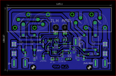
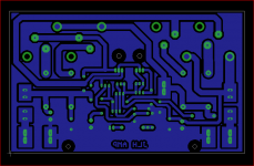
A few months ago I finished the construction of a power amplifier JLH 2005 (4xMJ15003).
From the beginning I noticed a certain lack of low frequencies, both in terms of extension and punch,.............
Hi! I would not have expected answers like this: THANK YOU!
CUMBB
the speakers: Yamaha ns10, sonus faber fm3, self-built OB (w 15 ", driver1.4" + horn)
amps jlh 2005, 2 channel, 2 double psu: 4x 19.5v not stabilized, transformer 500VA 4x18V, elco 4x33000uF 40V Epcos with by pass Visahy mkp 1837 100nF.
Also I am convinced that in the upper middle jlh is better than the hiraga, but nevertheless the basses do not find them ....
AndrewT
If you are referring to the feeding filter see above, if you are more specific, please.
GABARDELA
... I do not doubt, but this is what happens to me ... unfortunately!
Thanks
Mleod
I do not think it is a problem of damping factor because some low noite is there, but definitely without phatos, strength, presence .... Listening to the drums of drums the high notes are beautiful, present, when it touches the bass drum .... . Help! it is as if this were 6 meters farther behind ... And just one example, naturally also the other musical instruments suffer the same effect.
Actually it would seem there was something that cuts the frequency down, like a filter ... mah!
Hello
Mleod
Actually it would seem there was something that cuts the frequency down, like a filter ... mah!
Hello
Mleod
Toooo much problems, I think;-)
All do complain, that the JLH, similar to the Hiraga, has no deeps. But it is not.
An other question: why an other amp, when it has to sound as all the other;-?
SE, or similar, sound much finer, with much more solution than a, every, complementary-pp. Has "space". The Hiraga, similar, has not. In the deeps too. That, in my mind, is one reason. The most misunderstand as less bass. The "build of" of the amp does influence very much the sound. SE much much more. But too complex the know-how to convey.
All these speakers are to tune. All these speakers are roaring. I am very sure;-)
In my mind, too, the damping factor is a problem very very very seldom. If, than higher the capacity of the psu;-) Or, better, tune the roaring speakers.-)
To get more "sound", as the Hiraga, in the deeps too, I would reduce the capacity.
Or, better, I would set 12 x 10 mF: sounds more fluid.
I would remove the bypass-100 nF.
Do you use lugs or crimps or other gray sounding stuff?
And I would use just 2 windings of the trafo. May be, than the deeps are just 2 meters behind;-)
I would connect the 2 psus. I would get a cleaner sound, more "one voice", one corpus, less rumpus;-)
I would not use lace. I would use solid core, 2 x 0,8 mm, or so: less noise.
I would reduce the distance speaker - speaker. To get ONE Voice, ONE corpus, ONE room. May be: 1,5 m or less!!!
I would focus the speaker 50 cm ahead the tip of my nose;>)
...
and so on, and so on, and so on;-)
LG
I do not think it is a problem of damping factor because some low noite is there, but definitely without phatos, strength, presence .... Listening to the drums of drums the high notes are beautiful, present, when it touches the bass drum .... . Help! it is as if this were 6 meters farther behind ... And just one example, naturally also the other musical instruments suffer the same effect.
Actually it would seem there was something that cuts the frequency down, like a filter ... mah!
Hello
Mleod
Hi
So how I understand you got a nice sound but the lower region (bass) lucks weight. Even so, you got some bass not heavy and deep enough, or we can say it is shy. Can you post some pictures inside of your amp. Do you have any capacitors on the PC boards after the PS cap banks? What type of hock up wires you use between the PS capacitors bank and the PC boars. Some silver plated Teflon wire tend to sound just like that you mentioned. I am serious. Also like bass heavy, fat sound. Because of that, I did run into problems like these with a few popular amplifiers was highly rated by other forum members. I can relate to your problem or situation. Let's try to do something with the amp, these not a cheap project just to disassemble it and give up. 🙂
@Mleod,
Like gaborbela and AndrewT say some pics and exact schematic with coMponent values of your build would make it easier to understand issue and make suggestions by experts and those that have already built.
Like gaborbela and AndrewT say some pics and exact schematic with coMponent values of your build would make it easier to understand issue and make suggestions by experts and those that have already built.
Europe is really a small village!I was. Shame you never met Kendall Perry now of silicon valley in the shop if you had visited. Westwood's shop existed since 1947, I was very lucky to work there. It was at first a hobby electronics shop. I think Kendall wrote for Elektor. He taught me current mirrors and the Crimson design. He was at Merton College. Also Michael Gerzon taught me plenty. Much modern digital is due to him. Solid State Logic mixing desks started at Westwood's. I live almost nextdoor to SSL.
As you might remember we repaired and improved many pieces of hi fi. I learnt how many designs could sound good where it looked they shouldn't. Equally the Radford HD250 didn't. One was in the window so long it changed colour. It's was a mystery as it looks so good on paper. The Nytech 252 would be worth cloning. He was from Radford.
Below is a rather interesting French design Gogny using 2N3055 to drive 50 watts into 1 ohms I think for ribbon tweeters. It is rather unusual in using a 3055 to drive a 3055 and points out gain is a problem when doing this. You should just about be able to read the idea. I think one side was for modern preamps and the other older Gogny designs. Also some ribbon feedback if not mistaken. It seems highly unlikely it was the right marriage. However to make a ribbon then ruin it's sound seems unlikely. Forgive the slight change of direction except 1967 and 2N3055 are the era. I have often speculated all it needs is a current source to the VAS. I have never really liked the Krell amps. I suspect although class AB I could like this Gogny. Note the shunt input feedback even with long tail pair.
Sorry this copy seems to be unreadable now! The circuit is just about readable and the magazine reference date. I was in Paris in May that year. It truely was France at it's most modern ever ( DS, Metro). I saw colour TV in 819 lines. In my mind best ever TV even including normal HD. Perhaps not as good as the Pioneer Plasma TV's if being strict.

I did not have the chance to go to your store, but since I deporn a lot of English material for years, I often heard about you on different forums.
unfortunately, I can not read the document but I understand the spirit of the scheme and I have already seen something similar somewhere, I would have to look (maybe at philips)
Fortunately, there is still a lot of interesting schemes to explore, but I do not think in modern structures.
I have a CPA 602 and CTA 252, they are great devices, audio innovation ALTO mk1, an ariston, a sugden, that happiness!
now, France is Devialet ...

I've been working for years on the JM Plantefeve scheme, he's an adorable gentleman, always ready to help understand things.
I'm really happy to have finally spoken to you and I hope we will have the opportunity to continue another time
You too. The French way of looking at things is closer to my own. I always liked Jean Hiraga's ideas. French engineering often is deceptively simple. The Citroen 2CV being a good example. Someone said of me " Nige takes a circuit and removes parts until it stops working ". In a way that's true. I then put the important part back in the circuit. Like good food less can be more.
Below is a silly design I did to see what is possible. It gave the same distortion at all levels as a OP604 op amp with complimetary feedback output stage ( Sziklai ). These are my notes to myself so forgive any mistakes or things that are not clear. The idea was a JLH with less 50 kHz distortion. The feedback from the sources to VAS is to reduce the last residual. Notice it has a DC offset of 33 mV. That seemed to be reliable. The 4000 uF non polar output capacitor was to prevent disaster in the testing phase. It's not a great use of FET's. If one has a heaphone amplifier I guess driving the shunt input side could be very good ( 75R ). Notice it is able to offer class A upto the level where most would be happy ( 0.7A ) and that it gives AB for peaks. Notice also that making the loop gain greater using 0R purple resistor gives more distortion than 47R. I think I chose 16R in the end. I have always thought that resistor is important. It is not negative feedback that we are talking about. Just how easy it is to drive. It most likely could be changed with a more capacitance to the bc of the VAS. Not sure that's the best idea. More likely increase Re and reduce Cbc. Notice the bootstrap CCS to the VAS collector is only 2u2. I found it was enough. It can be larger. The feedback ratios of 75R and 1K5 seem about right. The idea of the amplifier was to drive Quad ESL57's in an ideal way.

Below is a silly design I did to see what is possible. It gave the same distortion at all levels as a OP604 op amp with complimetary feedback output stage ( Sziklai ). These are my notes to myself so forgive any mistakes or things that are not clear. The idea was a JLH with less 50 kHz distortion. The feedback from the sources to VAS is to reduce the last residual. Notice it has a DC offset of 33 mV. That seemed to be reliable. The 4000 uF non polar output capacitor was to prevent disaster in the testing phase. It's not a great use of FET's. If one has a heaphone amplifier I guess driving the shunt input side could be very good ( 75R ). Notice it is able to offer class A upto the level where most would be happy ( 0.7A ) and that it gives AB for peaks. Notice also that making the loop gain greater using 0R purple resistor gives more distortion than 47R. I think I chose 16R in the end. I have always thought that resistor is important. It is not negative feedback that we are talking about. Just how easy it is to drive. It most likely could be changed with a more capacitance to the bc of the VAS. Not sure that's the best idea. More likely increase Re and reduce Cbc. Notice the bootstrap CCS to the VAS collector is only 2u2. I found it was enough. It can be larger. The feedback ratios of 75R and 1K5 seem about right. The idea of the amplifier was to drive Quad ESL57's in an ideal way.
Last edited:
Actually this elector 189 amplifier has thread on Polish forum Prosty rywal dla GainClona - DIY - Audiostereo.pl Just use google translation 🙂 .
Thank you. Here is another design that never was taken up except perhaps by Mullard. Better class B with interesting ways of working. I have seen it simplified with NE5534 input stage. I like the triple outputs which could be used for JLH TR1.
http://www.keith-snook.info/wireles... to class-B Amplifier Design by P Blomley.pdf
You too. The French way of looking at things is closer to my own. I always liked Jean Hiraga's ideas. French engineering often is deceptively simple. The Citroen 2CV being a good example. Someone said of me " Nige takes a circuit and removes parts until it stops working ". In a way that's true. I then put the important part back in the circuit. Like good food less can be more.
Below is a silly design I did to see what is possible. It gave the same distortion at all levels as a OP604 op amp with complimetary feedback output stage ( Sziklai ). These are my notes to myself so forgive any mistakes or things that are not clear. The idea was a JLH with less 50 kHz distortion. The feedback from the sources to VAS is to reduce the last residual. Notice it has a DC offset of 33 mV. That seemed to be reliable. The 4000 uF non polar output capacitor was to prevent disaster in the testing phase. It's not a great use of FET's. If one has a heaphone amplifier I guess driving the shunt input side could be very good ( 75R ). Notice it is able to offer class A upto the level where most would be happy ( 0.7A ) and that it gives AB for peaks. Notice also that making the loop gain greater using 0R purple resistor gives more distortion than 47R. I think I chose 16R in the end. I have always thought that resistor is important. It is not negative feedback that we are talking about. Just how easy it is to drive. It most likely could be changed with a more capacitance to the bc of the VAS. Not sure that's the best idea. More likely increase Re and reduce Cbc. Notice the bootstrap CCS to the VAS collector is only 2u2. I found it was enough. It can be larger. The feedback ratios of 75R and 1K5 seem about right. The idea of the amplifier was to drive Quad ESL57's in an ideal way.
I had a pair of esl 57 cooper quad powered by 2 Filson blocks, it worked great.
I sold them(esl57) to a person who had ten pairs and who wanted an eleventh.
I will try to mount your amp on my table to see what it gives.
I have never seen this topology and I am naturally curious 🙂
~ Classic CD Player Modification & Modernisation ~
it is thanks or because of him that I started with tda 1540 then 1541.
it's not a beer that I owe him, it's a barrel!
@Mleod,
Like gaborbela and AndrewT say some pics and exact schematic with coMponent values of your build would make it easier to understand issue and make suggestions by experts and those that have already built.
same, no better, no more
Greetings to everyone!
A few months ago I finished the construction of a power amplifier JLH 2005 (4xMJ15003).
From the beginning I noticed a certain lack of low frequencies, both in terms of extension and punch, for the rest nothing to say. Immediately I tried to replace three types of speakers (BR, closed and OB) thinking that the problem was that, but above all connected to the Open Baffle speakers (not very performing in this range, but those that I am most interested in using transparency issues) , I could not get any appreciable improvements.
Then for a while I had to suspend the business.
Recently, however, I picked up the thing and after having documented I decided to intervene on three targets: substantial increase in input capacity, closed the electrolytic capacitor of NFB and added a capacity (330pf) to the transistor driver BD139.16 to implement the Miller effect.
Result: no results ... nothing, everything as before, if not a slight increase in overall accuracy.
At this point, to look for confirmation, I tried a direct comparison with an old Hiraga Class A: unfortunately my impressions were correct lack the bass, the deepest are completely absent ... it's a shame because the rest would have much to to be appreciated.
Now I would like, if someone could give me some suggestions to solve the situation once and for all, because I would be sorry to dismantle the whole for a deficit that theoretically should not have, but in fact substantially affects the performance of such a good amplifier.
Thanks in advance, especially to those who could help me.
Greetings to everyone!
Mleod
I would first closely look at the input capacitor.
It is important that the capacitor is 1uF and of the correct type.
I am using "Philips 1uF MKC 100V." With good results in both measurement and listening.
Let us know if that helps.
-Dan
- Home
- Amplifiers
- Solid State
- JLH 10 Watt class A amplifier