I was thinking of trying a single stage with the LTC6090 on an SOIC-->DIP adapter, using PCBs from this project of mine:
4-channel gain stage with power supply
If I could find a dual amp in a DIP-8 package that could handle at least +/- 22V rails I would try that, too.
4-channel gain stage with power supply
If I could find a dual amp in a DIP-8 package that could handle at least +/- 22V rails I would try that, too.
Last edited:
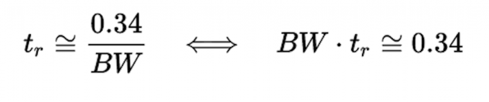
Have some fun: apply the bandwidth-risetime equivalency principle (link to Wikipedia)

to the LTSPICE plots in post #21. Risetime from the transient analysis plot, and bandwidth from the AC analysis plot. This circuit's closed loop gain, in decibels, is
_
to the LTSPICE plots in post #21. Risetime from the transient analysis plot, and bandwidth from the AC analysis plot. This circuit's closed loop gain, in decibels, is
- Av,cl = 20 * log10(R3/(R1+R2)) = +30.6 dB
_
Attachments
I was thinking of trying a single stage with the LTC6090 on an SOIC-->DIP adapter, using PCBs from this project of mine:
4-channel gain stage with power supply
If I could find a dual amp in a DIP-8 package that could handle at least +/- 22V rails I would try that, too.
LME49860? It's just a LME49720 binned for 44 V between the rails vs 36 V. Heck you could just try a few DIP 49720's and see if they pass muster. (the 860 and 720 are literally the same silicon)
Much easier to read, thanks. LME49710 is nice driver - you will need dual PSU now at two different rails.
Here is 90vpp design I just came up with. Still 5 transistors and now 0.0076% THD for 90vpp into 10k.
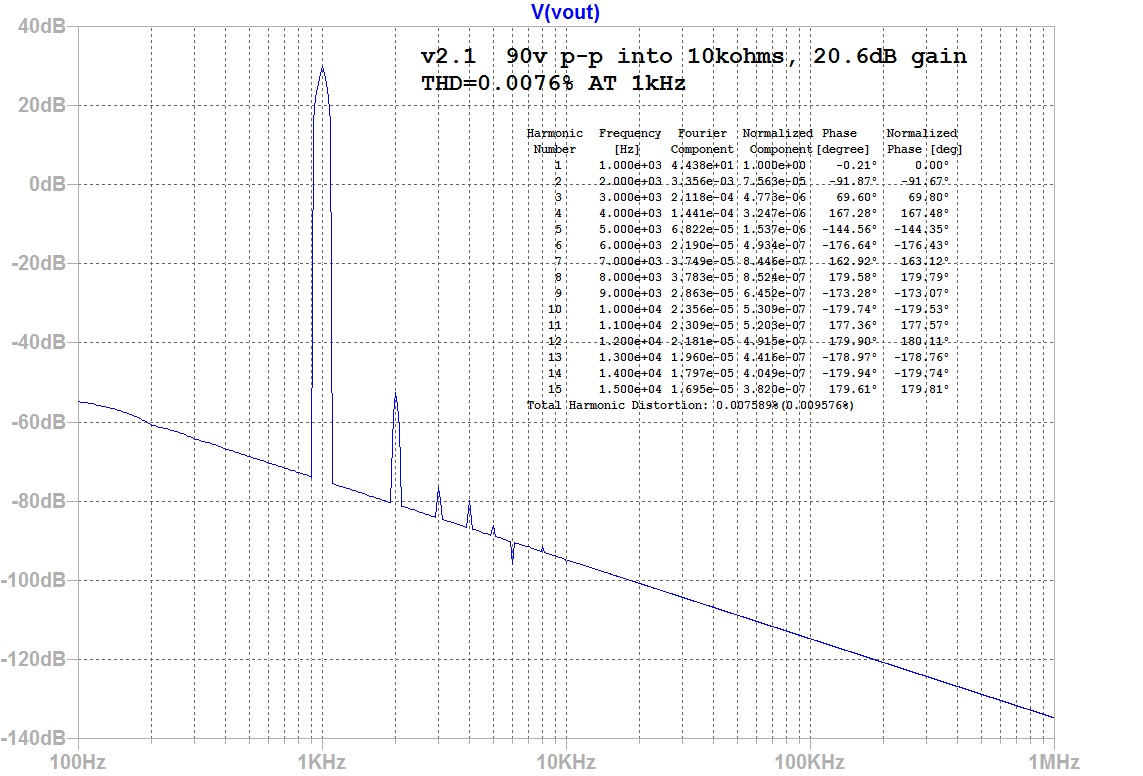
Here is 90vpp design I just came up with. Still 5 transistors and now 0.0076% THD for 90vpp into 10k.
And a bit slower but still looks like it'd be more than functional in this application: ADA4522 (55V rail-to-rail) or ADA4700. But I'd be greedy and try to build a composite (admitting that their low bandwidth complicates the matter). Looking up, basically BesPav hits that one fairly well.
Or, heck, given the 20 dB gain gives you some phase margin budget, a bootstrapped front end opamp and a discrete PP class A output buffer on the back end (or grab something from Jim William's compendium of good ideas).
Or, heck, given the 20 dB gain gives you some phase margin budget, a bootstrapped front end opamp and a discrete PP class A output buffer on the back end (or grab something from Jim William's compendium of good ideas).
Last edited:
If I can live with 44V Vs,max there is the OPA275 in a PDIP-8 package:
OP275 Datasheet and Product Info | Analog Devices
Ah, yea, the LME49860 on +/-22V looks like a winner and has a higher GBP. I would need to put it on an SOIC to PDIP adapter.
The ADA4522-2 is a bit GBP limited, like the OPA275, but can operate at +/-27.5V giving a little more headroom. Since none of these are rail-to-rail, you have to keep in mind where it will clip WRT the rail voltage.
Since my gain stage board has 4-channels I can run the gain through two stages and still accommodate two separate channels. All of the ICs must operate from the same supplies, however, so no 2-stage high/low Vs arrangement is possible.
Last edited:
opa275 : about 41.6vp-p on 44v
opa604: 42vp-p on 48v (the dual pdip version is still around but expensive)
lme49860: 42vp-p on 44v
The lme has clearly better specs though. The opa604 has the advantage of being a jfet input one, which can come in handy.
opa604: 42vp-p on 48v (the dual pdip version is still around but expensive)
lme49860: 42vp-p on 44v
The lme has clearly better specs though. The opa604 has the advantage of being a jfet input one, which can come in handy.
Have some fun: apply the bandwidth-risetime equivalency principle
Complicated correction, SR mostly defined by LTC6090’s output stage.
Much easier to read, thanks. LME49710 is nice driver - you will need dual PSU now at two different rails.
You’re welcome!
No, just 2x zener+cap+resistors for +-15 Volts from +-70 V rails.
The opa604 has the advantage of being a jfet input one, which can come in handy.
Jfet input with a such low-resistance source (2 kOhm at inverting input) aren’t advantage. Just simulate noise.
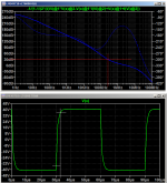
Have some fun: apply the bandwidth-risetime equivalency principle to the LTSPICE plots in post [#20]. Risetime from the transient analysis plot, and bandwidth from the AC analysis plot.
Bandwidth at the closed loop gain is 250 kHz by eyeball (red intersection)
10% - 90% risetime is 2 usec by eyeball (white abscissa).
BW * RT product is 0.5, pretty close to theoretical prediction (0.34)
_
Attachments
How is this thing even stable?Bootstrap almost any opamp with two TO92's and four resistors to get 70v p-p.
it isn't for a noise gain of 2 (inverting -1) but fruther away from that gain it should get better behaved
beware trying to sim, most macro models don't correctly show PS pins affecting compensation when in real 5-pin op amps the Cdom is connected to one of the PS rails
beware trying to sim, most macro models don't correctly show PS pins affecting compensation when in real 5-pin op amps the Cdom is connected to one of the PS rails
How is this thing even stable?
I have 33pF NP0 across FB resistor. Seems to work fine with no oscillations as observed on scope trace.
Which op-amp did you use?I have 33pF NP0 across FB resistor. Seems to work fine with no oscillations as observed on scope trace.
Which op-amp did you use?
It’s all detailed in my thread post 1.
Surjan Dogran's Easy Peasy 70v peak-peak Opamp for $1
JRC5534D. Actually it was 33pF silver mica not NP0.
Last edited:
I wonder how this bootstrapped op amp recovers from clipping.
This scheme is prone to hooking effects and unpredictable behavior; The +Vs and -Vs at the op amps are ok only if the amp is ok, for the amp to work right the +/- Vs must be right.
The equations are fine, but work only if the amp does work right.
Experienced engineers know that "if anything can go wrong, it will".
I wonder how many diyers got good results with this.
Personally I would not commit my loudspeakers to this contraption.
There’s a nice article here pointed out to me by another member in my thread detailing the potential pitfalls (latch up) and how to implement so that it is safe to use. There is also a table of pianos that are inmune to phase reversal latch up.
https://m.eet.com/media/1152270/24127-45890.pdf
https://m.eet.com/media/1152270/24127-45890.pdf
Bootstrapping an opamp is a good technique if you really need the extra voltage swing. But it brings extra complexity and dangers (it's sensitive to latch up, phase reversal) that might as well be avoided if an opa604 is sufficient.
I recall that Boonton used a boot-strapped NE5534 in the output section of the 1120's generator -- and it will easily put out 16V @0.0007% THD.
The Boonton is not quite so simple. Is two lamps with diamond buffers capable of driving a 100 Ohm load to 16v rms in btl.
Interesting. I'm pondering PSRR and the effect of bootstrapping on the Miller compensation...
I can't seem to find a graph of PSRR for each rail of a 5534.
I'm thinking about this as I go here. I am wondering where the compensation is coming from if not from Miller. If the op-amp uses a different compensation scheme such that the common-mode PSRR, if you will, does not affect the compensation then ok. But I'm not sure which op-amps fit this criteria. Otherwise the compensation has to happen somewhere else like the input differential stage which is now seeing the output swing instead of the miller stage.
Interesting.
Last edited:
- Status
- Not open for further replies.
- Home
- Source & Line
- Analog Line Level
- op-amp based, high-gain, high rail voltage, preamp