The attacks are smoothed (notes are rounder, less articulation) and vocals become too thin, clearness is better than with 13 or 15 ohms alone.
L-Pad don't seem to be for this speaker, maybe the Ferrofluid of the tweeter is good enough (16 years).
I note than the 1 ohm put before the 10ohm//1 uF give better result than the added 1R/15R L-pad.
Have to try 14 ohms in serie and stop after. It seems I need more tools : take measures and go for EQ, better to sell them for a better specialist than me.
Last edited:
The attacks are smoothed (notes are rounder, less articulation) and vocals become too thin, clearness is better than with 13 or 15 ohms alone.
The more important thing for a speaker to sound good is the blending of the 2 drivers, not the FR or removing of peaks. That's why changing a working filter cannot be partial.
L-Pad don't seem to be for this speaker, maybe the Ferrofluid of the tweeter is good enough (16 years).
I note than the 1 ohm put before the 10ohm//1 uF give better result than the added 1R/15R L-pad.
Of course. That's the point of this thread. L-PAD vs single resistor. But of course you cannot compare 1R at input versus 1R/15R L-PAD because the level of attenuation is greatly different. At least you have to compare 5R at the input versus 1R/15R L-PAD for more or less the same attenuation.
Have to try 14 ohms in serie and stop after. It seems I need more tools : take measures and go for EQ, better to sell them for a better specialist than me.
You have liked 15R at input before. I think you can go with 13R3 but this time you have to restore the phase coherence by reducing the 14.2uF
But yes, many commercial speakers are too expensive for the driver quality they use 😀
If you think this went too far but it was the right direction, try increasing the parallel resistance and then adjusting the level with the series resistor.The attacks are smoothed (notes are rounder, less articulation) and vocals become too thin, clearness is better than with 13 or 15 ohms alone.
Hi AllenB,
thank you for the advice. The L-Pad I tried : R1= 12 with R2=33 but R2 was not near R1 because R1 was at the beginning of the crossover and R2 at the end...
I understand more with the on line l-pad calculator and the good advices here. but don't understand why the genuine value choosed is witha //1uF : we don't need to increase the beginning of the curve after 2600 hz (crossover) when it falls after ?
And the second one: with the 10 ohms at the beginning, the added L-Pad of yesterday : R1=1 & R2=15 at the end of the crossover near the driver.
Your advise is to stay with that but adjust R2 (with more value) and play with 1 or two 2 ohms with the R1 for volume adjust : and the initial 10 ohms is keeped ?
I think an attenuation near 2 DB is good, but don't solve main issues. I just bought a second hand ECM8000 (not for that but for a futur project) but don't have an usb dac for acquisition yet...I'm a snail !
The LPAD presents a "constant" impedance to the crossover - more constant in fact than the tweeter alone would do. The LPAD also presents a lower source impedance to the tweeter. An amplifer alone has a typically very low source impedance. Adding any resistor in series will present the speaker with that impedance. (one could consider then the damping factor, etc. if one was so inclined). Adding the shunt resistance of the LPAD means that the overall source impedance seen by the speaker/tweeter is the parallel combination of the two resistors of the LPAD, which will be much lower than the single series resistor value.
What is between the 10 ohm, the series capacitor and the l-pad?Your advise is to stay with that but adjust R2 (with more value) and play with 1 or two 2 ohms with the R1 for volume adjust : and the initial 10 ohms is keeped ?
This seems to be a high Q resonance, it will take something high Q to fix it without taking out everything around it.]I think an attenuation near 2 DB is good, but don't solve main issues.
Quote :
thank you for the advice. The L-Pad I tried : R1= 12 with R2=33 but R2 was not near R1 because R1 was at the beginning of the crossover and R2 at the end...
That doesn't look correct, I only go by first look, it probably messes the crossover and speaker up. They should be in the exact configuration, last thing connected to the speaker.
What is between the 10 ohm, the series capacitor and the l-pad?
This seems to be a high Q resonance, it will take something high Q to fix it without taking out everything around it.
hI AllenB,
All the LR4 crossover seen in the page two of the famous well known thread "acoustical filter for tweeter". In serie it is : About 14 uf and 8uF after the first shunt L ! (shematic on page two).
Adding the shunt resistance of the LPAD means that the overall source impedance seen by the speaker/tweeter is the parallel combination of the two resistors of the LPAD, which will be much lower than the single series resistor value.
Well R1//R2 values of a L-Pad is < R (alone in serie)
but when the tweeter is ferrofluided ?
Is a klimbing impedance for the tweeter is a brighter sound ? My amp can drive "complicate" drive : it's a Chord... the amp of Paul Mac Cartney (joke, he has it...he had it)
http://www.diyaudio.com/forums/multi-way/240636-acoustical-filter-tweeters-2.html#post3592382
Last edited:
Here is a tweeter with impedance (green), and a fourth order filter (blue).
A ten ohm resistor next to the amp gives the result in red, next to the driver gives the result in magenta (the filter is working into a higher impedance so the filter damping is changed).
However, an L-pad next to the driver can be adjusted to damp the filter among other things. After a little tweaking (light blue).
Attachments
Very interresting : electric capture with Dayton 's tool or a micro, or crossover simulator ?
I understand why there is a 1uF // with the 10 ohms : it's to make the curve flater at the beginning because the curve deep in the low-pass section !
It seems to be harder to make the curve deep at the middle or the end !
I understand why the brighness is always here : with increasing the resistor value I take off more of the beggining curve than after whhere the brighness is (5K hz and after...if i look at the measure of Stereophile with the Lynfield 500L : same mid and tweeter)
Real driver, simmed crossover. It's all the same for this. We know tweeters are different and some combinations of crossover have unexpected results. We're careful, even maybe hesitant to say that the cap lifts the highs, the resistor pads it down etc.
In this simple example I used the red response from yesterday, and the first plot shows the resistor next to the amp - 10, 7, 5, 3.5 ohms.
Next it stays at 10 ohms, but I have used a capacitor - 0.5u, 1u, 3uF.
Then I kept the 1uF capacitor and changed resistors - 10, 7, 5, 3.5 ohms.
In this simple example I used the red response from yesterday, and the first plot shows the resistor next to the amp - 10, 7, 5, 3.5 ohms.
Next it stays at 10 ohms, but I have used a capacitor - 0.5u, 1u, 3uF.
Then I kept the 1uF capacitor and changed resistors - 10, 7, 5, 3.5 ohms.
Attachments
hI AllenB
I try today to be sure :
2x // 27 ohms : 13.5 ohms.
and a L-pad with the same original filter attenuation of 7 DB (10 ohms): R1 : 4.7 & R2: 6.8 ohms
all without the 1uF. Will try too the reducing to 1.8 uF of the 6 uF cap in the first cellul to see if the phase match better with the new attenuation (Jay)
Well the set up of a filter is a fabulous thing...when you don't understand what you do.
The L-Pad is equal to the 10 ohms in attenuation but the impedance curve is not the same : the sound too. Same clarity, but a little less brighness and little more bass. It is - 7 db. - 9.5 db with 15 ohms is too much. i have to try 14 ohms or a L-Pad which is its equivalent attenuation (but no standard value to make it ! I was not really happy with 12R7 made with 10+2R7...db attenuation is very little between 10 or 15 but you can hear it.
I put the L-PAD is in the beginning of the tweeter filter, not near the driver. I plan to add 1 ohm in front of the L-PAD. The last 8 uF caps are new : MKP/oil Amphom + Al/PiO Amphom, the MIT RTX polystyren stay with the 14 uF of the first stage of the LR4.
Not the time today to try the 14 ohms... I can't imagine the time we can spent with an active EQ where you can change what you want...a life !
pleasant hobby, not good for listen music because we spent a lot of time...but great time !😀 Fellows I know much today than 1 month ago with your help🙂.
to be continued...
Last edited:
oups...seems to have replace R2 with standard 5R6 to have 7.7 db attenuation cause now it's less than 7 db with the R2 at 6.8 according the calculator ! I bought the resistor in a speaker shop who calculate it for me according the genuine 10 ohms in serie (- 7 db) ! better to calculate myself before !!!!!
I seen that because the sound seem slighty clearer (but with no adding brighness) than the original set up. I change my mind with L-Pad : seem better for the moment... i have to work a littler more.
I seen that because the sound seem slighty clearer (but with no adding brighness) than the original set up. I change my mind with L-Pad : seem better for the moment... i have to work a littler more.
Last edited:
Question related to L-pad.
I have a pair of the Pyramid Super Tweeters in stand-alone housings. I currently have them paralleled with my Cerwin Vega VS-150 speakers. They sound good, but could use attenuation. If I get a variable L-Pad, can I still maintain that parallel configuration and not affect the signal that the Vega is getting? Can i series them so my amp sees 16ohm instead of 4? Will that affect the frequency response? More importantly, will it appreciably affect how my speakers sound?
With an L-Pad, do I need to worry about the wattage that much? My amp can push 350wpc, but with the vegas I never need to crank it that loud.
Would I be better off scrapping the L-pad idea and just installing an additional amp to run the super tweeters?
Charles.
If you have them in parallel and change them to be in series you'll lose 6dB. This is before you consider effects from the filters.
If you had 6dB to lose this will make them easier to drive but sometimes an L-pad makes designing the crossover more convenient. If this isn't a problem I'd consider it.
If you had 6dB to lose this will make them easier to drive but sometimes an L-pad makes designing the crossover more convenient. If this isn't a problem I'd consider it.
Question related to L-pad.
...
With an L-Pad, do I need to worry about the wattage that much? My amp can push 350wpc, but with the vegas I never need to crank it that loud.
Would I be better off scrapping the L-pad idea and just installing an additional amp to run the super tweeters?
Charles.
Perhaps this will give you some insight into how an L-Pad is placed into the circuit -
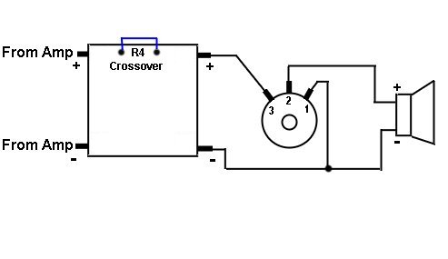
Keep in mind this second graphic was created for a different purpose, but it still serves in this circumstance.
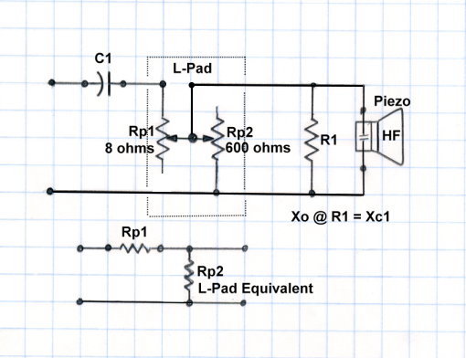
As you can see, the L-Pad is the equivalent to a Series and Parallel Resistor that attenuate the signal, but it takes it one set farther, The Resistive Components are chosen to maintain a fixed nominal impedance across the range.
Though, using 8 ohms as an example, it doesn't perfectly hit 8 ohms across the full range of adjustment, but it comes very very close.
Of course, the impedance of the speakers is not perfectly 8 ohms across the frequency spectrum, but the parallel resistive aspect will help maintain closer to a fixed 8 ohm impedance.
Do you have some type of crossover element in the Super-Tweeter now? If so ... what?
The impedance of various driver components, each with its own crossover elements, do not add. Each has its own frequency range and therefore at those frequencies it is the only element in the circuit (within a reasonable context).
If there is no crossover component between the tweeter and super-tweeter than the impedance is reduced when the Tweeter and Super-Tweeter are combined. Keep in mind that when the impedance of the tweeter combination changes so does the frequency location of the crossover.
For example, if the crossover to an 8 ohm tweeter is 3000 hz, then when you combine two 8 ohms tweeters without a crossover between them, then the crossover frequency shifts up to about 6000hz. That will leave a gap in the frequency range between 3000hz and 6000hz.
The above represents the Capacitive element of the Crossover. If there is a parallel Inductive (coil) element it moves in the opposite direction. The Coil based apect of the crossover drops down to 1500hz.
In other words, when impedance of the crossover load changes, the crossover becomes completely messed up.
Just a few thoughts.
Steve/bluewizard
Last edited:
Sorry to resurrect, but this was the closest I could find to my topic...
Anyway, can I use an 8-ohm L-Pad on a crossover with a 16-Ohm tweeter? It seems the answer is yes, I just have to factor the different resistances (tweeter and L-Pad) when designing the X-Over, right?
I don't suppose there's a nifty calculator for all this somewhere I've missed?
Anyway, can I use an 8-ohm L-Pad on a crossover with a 16-Ohm tweeter? It seems the answer is yes, I just have to factor the different resistances (tweeter and L-Pad) when designing the X-Over, right?
I don't suppose there's a nifty calculator for all this somewhere I've missed?
Well you can do anything, but why not just use a 16 ohm L-Pad?Sorry to resurrect, but this was the closest I could find to my topic...
Anyway, can I use an 8-ohm L-Pad on a crossover with a 16-Ohm tweeter? It seems the answer is yes, I just have to factor the different resistances (tweeter and L-Pad) when designing the X-Over, right?
I don't suppose there's a nifty calculator for all this somewhere I've missed?
If you determine how much attenuation you need, you can use a Fixed L-Pad that can be calculate at the bottom of this webpage Link -
Crossover Design Chart and Inductance vs. Frequency Calculator(Low-pass)
For this you can use an impedance you want for the speaker.
And here is a source of 16 ohm Variable L-Pads -
Speaker L-Pad Attenuator 50W Mono 3/8" Shaft 16 Ohm
Parts Express Speaker L-Pad Attenuator 100W Mono 3/8" Shaft 16 Ohm
I'm sure I can find others if I have too.
Steve/BlueWizard
- Status
- Not open for further replies.
- Home
- Loudspeakers
- Multi-Way
- Lpad v single resistor