Sorry Bimo,i can't think so.I think because critics from some people to showing their superiority.
They do not want help DIY community to make better design or share their design.

Sorry to bother you again Prasi. Since these boards are so small, can you copy and paste layout to make two side by side for a stereo board that is 100mm x 40mm? Please keep power connectors independent. This would reduce board fab costs by 2x as price for under 100mm x 100mm is all the same
Thanks,
X
Thanks,
X
Sorry to bother you again Prasi. Since these boards are so small, can you copy and paste layout to make two side by side for a stereo board that is 100mm x 40mm? Please keep power connectors independent. This would reduce board fab costs by 2x as price for under 100mm x 100mm is all the same
Thanks,
X
Good observation, a question, so in practice Prasi could fit 4 boards insde those 100x100mm for the same price?
Probably would have to add a milled up break path in the board so the two stereo pairs can be broken into two halves, not sure what that would add to the cost?
Last edited:
You have to be careful here not to make it look like you are making more than one PCB per board. Milled break- apart channels are a no no. The copied amps will need lettering to say "left" and "right" channels to be legit.
Oh I see, so if we want to add 4 amp boards into one we ought to mark each one something like: Front-L, Front-R, Rear-L, Rear-R
Would that pass and let us use panelization or would it look too shallow? Perhaps adding a few tiny dummy SMD's to distinguish each amp pair perhaps will do.
Would that pass and let us use panelization or would it look too shallow? Perhaps adding a few tiny dummy SMD's to distinguish each amp pair perhaps will do.
Last edited:
no problem x,Sorry to bother you again Prasi. Since these boards are so small, can you copy and paste layout to make two side by side for a stereo board that is 100mm x 40mm? Please keep power connectors independent. This would reduce board fab costs by 2x as price for under 100mm x 100mm is all the same
Thanks,
X
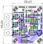
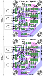
here you go. I kept 1 mm gap between PCB, so one may manually cut the PCB if required.
otherwise identical boards on top and bottom.
regards
Prasi
Attachments
Oh I see, so if we want to add 4 amp boards into one we ought to mark each one something like: Front-L, Front-R, Rear-L, Rear-R
Would that pass and let us use panelization or would it look too shallow? Perhaps adding a few tiny dummy SMD's to distinguish each amp pair perhaps will do.
Panelization by v-scoring or any other method of separation by board houses doesnt work, they will charge higher prices. If one is ready to separate the PCB manually, it doesnt matter , one could have 2 or even 10 board designs in same 100 x 100 mm board area.
Just checked it on pcbway.com
I wonder if they will raise an eyebrow with the above as it looks like we are trying to panelize it. That's why I suggested adding words "Right Ch" and "Left Ch" and maybe remove extra screw 4 mounting screw holes in middle?
I wonder if they will raise an eyebrow with the above as it looks like we are trying to panelize it. That's why I suggested adding words "Right Ch" and "Left Ch" and maybe remove extra screw 4 mounting screw holes in middle?
try and place the order, you wont be bothered. Only when you ask them to separate the boards by V-score or tab-routing, they will charge extra.
regards
Prasi
Hi Prasi,
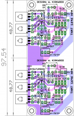
Not so fast. EasyEDA contacted me after I submitted the order to say that qnty 10 of the above THAT1646 (double) stereo amp counts as 20 PCBs. It's the obvious line and 8 screw holes I think. Furthermore, I think they may even want some traces to connect the two. Maybe a common ground?
Not so fast. EasyEDA contacted me after I submitted the order to say that qnty 10 of the above THAT1646 (double) stereo amp counts as 20 PCBs. It's the obvious line and 8 screw holes I think. Furthermore, I think they may even want some traces to connect the two. Maybe a common ground?
Hi Prasi,
Not so fast. EasyEDA contacted me after I submitted the order to say that qnty 10 of the above THAT1646 (double) stereo amp counts as 20 PCBs. It's the obvious line and 8 screw holes I think. Furthermore, I think they may even want some traces to connect the two. Maybe a common ground?
Oh, very clever of them.
I have connected the V+ and V- together, which can be separated if required by cutting the traces. ground is better where it is.
regards
Prasi
Attachments
Last edited:
Interesting development. I was about to change the Gerbers but EasyEDA told me that they will allow it this one time since I am already a good customer. 🙂 So I guess I get the first "momoblock" layout in the mail in a few days. The second one does look more polished as an "integrated" stereo amp though.
Interesting development. I was about to change the Gerbers but EasyEDA told me that they will allow it this one time since I am already a good customer. 🙂 So I guess I get the first "momoblock" layout in the mail in a few days. The second one does look more polished as an "integrated" stereo amp though.
Hmm. Interesting.
Its probably because, their subcontractor (jlcpcb.com) had already started manufacturing, otherwise there is no reason why they could not change gerbers.
Anyway, lucky you, to get 20PCBs at the price of 10😀. It could as well be 22 PCBs, if they ship the 11th PCB😉.
regards
Prasi
Hi Prasi,
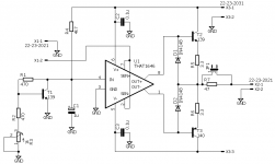
The THAT1646 headphone amp you made the layout for works very well. Bias is Rick stable and I set it at 100mA for Class A operation. Output offset is also very low at about 2mV. The PSRR is very nice. I don't hear any hum with a simple linear trafo and 7815/7915 regulator supply. I am running 2.2R emitter resistors vs 3.3R and I have a 10R output series resistor vs the 47R shown in the schematic. I have not measured it yet but I can say it has a very natural non fatiguing sound. I think the absence of global feedback makes a difference.

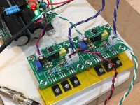
Amp undergoing first-sound testing - no issues, it fired right up the first time.

It's a very simple and quick amp to build.
Thank you again for your generosity with making layouts for us.
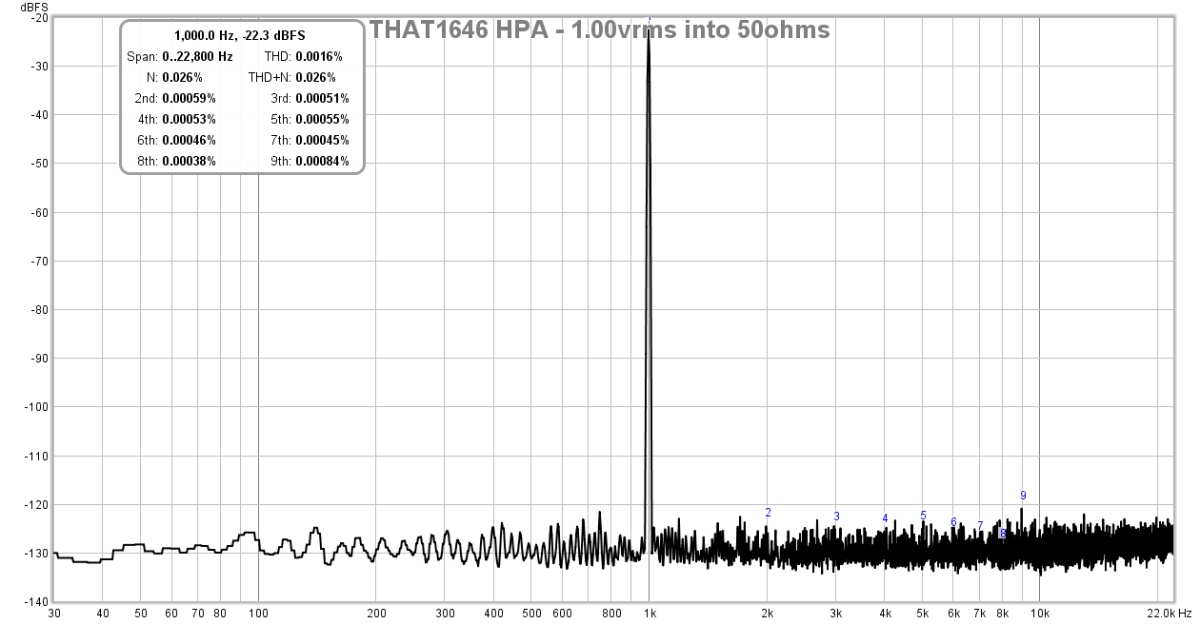
Edit. Ok a quick measurement with Focusrite 2i4 and 1.00vrms into 50ohm load, read out with 10:1 voltage divider. This confirms what I was hearing - a very neutral and quiet amp. Perhaps the lowest distortion amp I have ever measured. Basically at the limit of the Focusrite 2i4 (-130dB). Here is a case where I would need a nicer sound interface card if I wanted to measure it. Although if I removed the 10:1 voltage divider that would bring everything up 20dB. But it is very low distortion. I built this for a low distortion instrumentation amp actually so it is very good for that. I dunno, this sure is easier than making some of the designs floating around with about 35 BC550/560's to achieve similar distortion figures. There is feedback internal to the THAT 1646 IC, but none from the complementary slave output drivers.
The THAT1646 headphone amp you made the layout for works very well. Bias is Rick stable and I set it at 100mA for Class A operation. Output offset is also very low at about 2mV. The PSRR is very nice. I don't hear any hum with a simple linear trafo and 7815/7915 regulator supply. I am running 2.2R emitter resistors vs 3.3R and I have a 10R output series resistor vs the 47R shown in the schematic. I have not measured it yet but I can say it has a very natural non fatiguing sound. I think the absence of global feedback makes a difference.
Amp undergoing first-sound testing - no issues, it fired right up the first time.
It's a very simple and quick amp to build.
Thank you again for your generosity with making layouts for us.
Edit. Ok a quick measurement with Focusrite 2i4 and 1.00vrms into 50ohm load, read out with 10:1 voltage divider. This confirms what I was hearing - a very neutral and quiet amp. Perhaps the lowest distortion amp I have ever measured. Basically at the limit of the Focusrite 2i4 (-130dB). Here is a case where I would need a nicer sound interface card if I wanted to measure it. Although if I removed the 10:1 voltage divider that would bring everything up 20dB. But it is very low distortion. I built this for a low distortion instrumentation amp actually so it is very good for that. I dunno, this sure is easier than making some of the designs floating around with about 35 BC550/560's to achieve similar distortion figures. There is feedback internal to the THAT 1646 IC, but none from the complementary slave output drivers.
Attachments
Last edited:
Thank you for doing such a nice layout and for the design credit. I appreciate it.
This link provides a circuit description of the original HPA design: Dual Class-A Line and Headphone Output Board Documents - Pro Audio Design Forum
Best;
Wayne
This link provides a circuit description of the original HPA design: Dual Class-A Line and Headphone Output Board Documents - Pro Audio Design Forum
Best;
Wayne
- Status
- Not open for further replies.
- Home
- Amplifiers
- Headphone Systems
- ESP HPA