I'm working on the design for a push-pull ultra-linear amplifier with 2 6550/KT88 tubes per channel. This question is not specific to this particular design, however, and only concerns the ultra-linear topology of the final stage.
Everything I have read indicates that the weakest link in ultra-linear design is the transformer and the primary winding design. In particular, inferior transformer quality can cause various issues with high frequency response.
It occurred to me that a standard ultra-linear tap could be replaced with a voltage divider (resistor network) between the center tap (B+/AC Ground) and the plate supply on each output tube. Presumably one would need to use non-inductive resistors with tight tolerances. Am I wrong to think this would eliminate some of the concerns associated with the transformer design?
Can someone explain why this isn't done, or the potential complications with such a design? Thank you!
Last edited:
It occurred to me that a standard ultra-linear tap could be replaced with a voltage dividerAm I wrong
to think this would eliminate some of the concerns associated with the transformer design?
For low distortion, the screens should be fed from a low impedance source.
Some have used a buffer. http://www.pearl-hifi.com/06_Lit_Ar.../Broskie_John/Ultra Linear Output Stages.pdf
The problem is that the screen grid draws highly non-linear current. Peaking greatly when the plate V drops below the screen grid V. So a simple resistive divider will not work as planned.
What is usually done is to use the resistive divider to control the gate of a Mosfet follower stage, which then controls the screen grid (via the low impedance source terminal).
If the R divider is configured to keep the screen V below the plate V at all times (divider between the plate V and some lower fixed screen V supply) (note: this is NOT the case for conventional UL xfmrs!) then the Mosfet drain can be returned to the plate (instead of the B+). This has the advantage of returning the screen grid current (through the Mosfet) back to the plate circuit, greatly improving linearity.
This also increases the output power since screen grid current is routed 100% through the output xfmr. Normal UL only returns effectively 40% of the screen grid current to the OT. And connecting the Mosfet follower drain to B+ returns nothing to the OT, so that will be somewhat lower power and higher distortion than xfmr tapped UL.
This is not generally practical for high screen V tubes (ie, "audio" tubes), but should work well for low screen V TV Sweep tubes. This will of course reduce output power some versus the usual UL xfmr tapped version since screen V is kept lower.
It has been mentioned many times to try this, but I never hear any replies about the results. Some experimenting with the divider configuration for a particular tube is in order I would say.
Last edited:
The UL tap acting as feedback so the configuration is also called partial triode.
In this way the Rp is lower then pentode config, the efficency is lower but the distortion is better
In this way the tube curves seems to be close to the triode connection ( when the g2 is connected to anode=100% feedback and Rp goes down).
This is not possible to get with resistors.
At the end of the story with UL if you use a standard quality of trafo you can get a good results while in pentode connection it is more difficult and the trafo must be good because the impedance are different (higher)
Walter
AC-coupling ultra-linear transformer (capacitor?)
Another question concerning an ultra-linear push-pull output stage.
Suppose we have a tube with a screen grid voltage rating lower than its plate voltage rating by 0 to 40%. In order to operate the tube near its maximum plate voltage, we would normally use a transformer with a separate ultra-linear winding rather than a tap on the primary (such as the Acrosound TO-350). This way, the ultra-linear winding only acts as negative feedback (AC-coupled to the screen), and the DC screen voltage is provided by a separate DC supply.
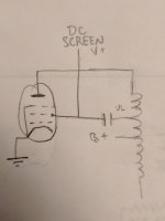
I am wondering, given a standard ultra-linear transformer (one primary winding with 40% voltage tap), could one simply use a coupling capacitor in series with the screen grid, connecting a separate screen DC supply after the capacitor? If not, why not?
Another question concerning an ultra-linear push-pull output stage.
Suppose we have a tube with a screen grid voltage rating lower than its plate voltage rating by 0 to 40%. In order to operate the tube near its maximum plate voltage, we would normally use a transformer with a separate ultra-linear winding rather than a tap on the primary (such as the Acrosound TO-350). This way, the ultra-linear winding only acts as negative feedback (AC-coupled to the screen), and the DC screen voltage is provided by a separate DC supply.
I am wondering, given a standard ultra-linear transformer (one primary winding with 40% voltage tap), could one simply use a coupling capacitor in series with the screen grid, connecting a separate screen DC supply after the capacitor? If not, why not?
Last edited:
Hi
in attach the schematic of a amp with TO-350
This is old, really is not necessary to have such connections because, as many does, also with EL34 we can reach 500 Vdc with UL conection without any problem.
You proposal is an headhace not necessary 🙂
Walter
in attach the schematic of a amp with TO-350
This is old, really is not necessary to have such connections because, as many does, also with EL34 we can reach 500 Vdc with UL conection without any problem.
You proposal is an headhace not necessary 🙂
Walter
Attachments
You proposal is an headhace not necessary 🙂
It is not necessary if you have a transformer like the TO-350, but I am wondering if it will work since I will be using an Edcor transformer.
For example, 6146 or 6QD6 with 600V B+ and 250V screen would require AC-coupling on the screen for ultra-linear operation.
Look this from Sowter and you have the solution
Replacement transformers for classic valve tube amps.
Walter
Replacement transformers for classic valve tube amps.
Walter
@ahanuban - you can try, but it may have issue with the screen voltage getting dragged down too much by the AC-coupled screen feedback voltage, which means very low output.
I'm a little confused what you mean by that (the screen voltage would be lowered by the feedback). How would the effect of capacitor coupling be different than using a separate transformer winding?
Look this from Sowter and you have the solution
Replacement transformers for classic valve tube amps.
Walter
Walter, I'm really looking for an answer to the question about capacitor coupling. At this time I am not interested in purchasing new output transformers from Sowter ($$$). 🙁
It wouldn't drag down the DC voltage. I think what he meant was that the (presumed) DC feed resistor to the screen grid is effectively in parallel with part of the transformer winding, i.e. it reduces the overall anode and screen load impedances, compared with 'ordinary' UL. However, this could be made negligible or 'designed in', so your idea is sound in principle, at least for class-A where average currents remain substantially constant.I'm a little confused what you mean by that (the screen voltage would be lowered by the feedback). How would the effect of capacitor coupling be different than using a separate transformer winding?
EDIT: And as Jazbo points out below, the down-going swing, when added to the DC screen voltage, could drop too low or even go negative. But of course, we assume you would choose a tapping point that did not go too far (this would normally qualify as distributed loading rather than ultra-linear).
Last edited:
What are the swings of the plate winding and the screen winding if B+ is 600V? Since screen grids are fed by a separate low B+ (250V in your example), what is the net voltage seen at the screen when the screen tap of the OPT swings to -250V...I'm a little confused what you mean by that (the screen voltage would be lowered by the feedback). How would the effect of capacitor coupling be different than using a separate transformer winding?
Another fact, looking on schematic.
The ac signals from cap goes to ground because the C on power supply of +dc screen is a short circuit in ac !!
Walter
The ac signals from cap goes to ground because the C on power supply of +dc screen is a short circuit in ac !!
Walter
- Status
- Not open for further replies.
- Home
- Amplifiers
- Tubes / Valves
- Alternative Ultra-Linear Connections?