Hi.
I have a problem with hum in my F5 I haven't been able to get rid of and I need some assistance to find out what to do.
There is a slight hum when I listen closely to the speakers and I haven't anything connected (only loudspeakers + RCA cables). My speakers have high sensitivity (98dBish). I can live with that slight hum but when I connect anything else there's a lot more hum.
I hope my attached picture make sense and that someone can give me any tips how to get rid of the hum.
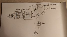
edit: more information about the amplifier. Its a dual mono setup, I use two 1x24V transformers, one to each rectifier bridge. the two bridges are placed on a PSU board with capacitors, (as you see on the pictures) then the card is connected to another card with capacitors via resistors.
I connected the first cards gnd to the starground as well as the other cards GND. Aslo all other GND (F5 input card, speaker and RCA common) is connected to the star ground. Each channel's star ground is connected to the ground loop breaker. Earth and chassis connected at the other end of the ground loop breaker.
the two channels / star grounds isn't separated by anything other than a wire.
All above should hopefully be clear by my sketch.
Would it be a good idea to add thermistors between the star grounds and the GND loop breaker to separate the two channels ground?
I tried (with a lot of hum) to connect both a B1 bufferts and also just via a potentiometer as well as directly to my phone.
I have a problem with hum in my F5 I haven't been able to get rid of and I need some assistance to find out what to do.
There is a slight hum when I listen closely to the speakers and I haven't anything connected (only loudspeakers + RCA cables). My speakers have high sensitivity (98dBish). I can live with that slight hum but when I connect anything else there's a lot more hum.
I hope my attached picture make sense and that someone can give me any tips how to get rid of the hum.
edit: more information about the amplifier. Its a dual mono setup, I use two 1x24V transformers, one to each rectifier bridge. the two bridges are placed on a PSU board with capacitors, (as you see on the pictures) then the card is connected to another card with capacitors via resistors.
I connected the first cards gnd to the starground as well as the other cards GND. Aslo all other GND (F5 input card, speaker and RCA common) is connected to the star ground. Each channel's star ground is connected to the ground loop breaker. Earth and chassis connected at the other end of the ground loop breaker.
the two channels / star grounds isn't separated by anything other than a wire.
All above should hopefully be clear by my sketch.
Would it be a good idea to add thermistors between the star grounds and the GND loop breaker to separate the two channels ground?
I tried (with a lot of hum) to connect both a B1 bufferts and also just via a potentiometer as well as directly to my phone.
Attachments
Last edited:
Both the input and speaker returns should go to the amplifier board input and speaker returns and not the star ground. They should also be close coupled with the other signal wire, that is, twisted or use coax for the input
Hi.
I have a problem with hum in my F5 I haven't been able to get rid of and I need some assistance to find out what to do.
There is a slight hum when I listen closely to the speakers and I haven't anything connected (only loudspeakers + RCA cables). My speakers have high sensitivity (98dBish). I can live with that slight hum but when I connect anything else there's a lot more hum.
I hope my attached picture make sense and that someone can give me any tips how to get rid of the hum.
edit: more information about the amplifier. Its a dual mono setup, I use two 1x24V transformers, one to each rectifier bridge. the two bridges are placed on a PSU board with capacitors, (as you see on the pictures) then the card is connected to another card with capacitors via resistors.
I connected the first cards gnd to the starground as well as the other cards GND. Aslo all other GND (F5 input card, speaker and RCA common) is connected to the star ground. Each channel's star ground is connected to the ground loop breaker. Earth and chassis connected at the other end of the ground loop breaker.
the two channels / star grounds isn't separated by anything other than a wire.
All above should hopefully be clear by my sketch.
Would it be a good idea to add thermistors between the star grounds and the GND loop breaker to separate the two channels ground?
I tried (with a lot of hum) to connect both a B1 bufferts and also just via a potentiometer as well as directly to my phone.
To start with it could be due to transformers, many of us have change the orientation or turned the torroids and fixed the issue, also the panel where the star ground is attached needs to be scratched shiny clean before the ground screw is tightened.
To start with it could be due to transformers, many of us have change the orientation or turned the torroids and fixed the issue, also the panel where the star ground is attached needs to be scratched shiny clean before the ground screw is tightened.
Transformer orientation could be tried though i connected them as i did by trying to phase out EMI.
The star ground isn't connected to the chassis (only via the ground loop breaker). The chassis to earth could perhaps get a treatment as you described.
I suspect it doesnt have anything to do with the chassis since the problem comes first when other gear is connected.
Both the input and speaker returns should go to the amplifier board input and speaker returns and not the star ground. They should also be close coupled with the other signal wire, that is, twisted or use coax for the input
I could certainly try that. It would probably make another star ground or ground point in the cards. What would be the difference from my star? I thought the main concern would be to get both speakers and inputs at the same potential and that would be at the point set by the power common, so thats why i tried to get all points at the same star.
Can you post a schematic and/or image of the amplifier PCBs? The main concern is to avoid current flowing in ground loops
Last edited:
Can you post a schematic and/or image of the amplifier PCBs?
Yes. Sure. I can do it tomorrow. It should be like my sketch but more capacitors at both boards and more resistor's in parallel. Nothing really special about it.
But I'll give you a picture and schematics tomorrow.
Edit. Sorry I misread PCB for PSU.
Schematics for the amplifier is the standard one. All is the same as the standard boards sold via diyaudio except for the GND as described
Last edited:
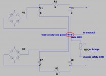
speaker gnd goes from amp pcb
each PSU having own NTC or bridge combo , going from main GND point to chassis safety GND
OK. Ill try moving the in and output common to amp board.
Ill also try adding the thermisors inbetween the two boards.
Post1Hi.
I have a problem with hum in my F5 I haven't been able to get rid of and I need some assistance to find out what to do.
There is a slight hum when I listen closely to the speakers and I haven't anything connected (only loudspeakers + RCA cables). My speakers have high sensitivity (98dBish). I can live with that slight hum but when I connect anything else there's a lot more hum.
I hope my attached picture make sense and that someone can give me any tips how to get rid of the hum.
edit: more information about the amplifier. Its a dual mono setup, I use two 1x24V transformers, one to each rectifier bridge. the two bridges are placed on a PSU board with capacitors, (as you see on the pictures) then the card is connected to another card with capacitors via resistors.
I connected the first cards gnd to the starground as well as the other cards GND. Aslo all other GND (F5 input card, speaker and RCA common) is connected to the star ground. Each channel's star ground is connected to the ground loop breaker. Earth and chassis connected at the other end of the ground loop breaker.
the two channels / star grounds isn't separated by anything other than a wire.
All above should hopefully be clear by my sketch.
Would it be a good idea to add thermistors between the star grounds and the GND loop breaker to separate the two channels ground?
I tried (with a lot of hum) to connect both a B1 bufferts and also just via a potentiometer as well as directly to my phone.
there's a mistake in the Zero Volts line.
The two plus and minus supplies meet at the zero volts line.
You have broken that line and taken the left side to a remote star. This is wrong.
The zero volts MUST connect to the smoothing caps immediately to the right.
The output from these smoothing caps must be at the opposite end from the three input connections.
There is another mistake.
The signal input is made with two wires.
You have taken one wire straight to the amplifier PCB input pads.
You have taken the other input wire to a remote star. This is wrong.
The input is two wires. These two wires must remain close coupled along their whole route from input socket to amplifier PCB.
Last edited:
Post1
there's a mistake in the Zero Volts line.
The two plus and minus supplies meet at the zero volts line.
You have broken that line and taken the left side to a remote star. This is wrong.
The zero volts MUST connect to the smoothing caps immediately to the right.
The output from these smoothing caps must be at the opposite end from the three input connections.
There is another mistake.
The signal input is made with two wires.
You have taken one wire straight to the amplifier PCB input pads.
You have taken the other input wire to a remote star. This is wrong.
The input is two wires. These two wires must remain close coupled along their whole route from input socket to amplifier PCB.
Thanks Andrew
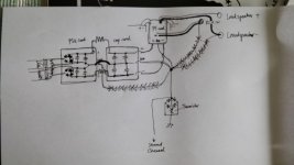
Something like this?
I redid the input and output as previous post suggested with huge improvement (still not 100 perfect).
I haven't put in the thermistors in series with the two star grounds. Would you suggest doing that?
The attached image is pretty blurry, i hope it still shows what i wanted to illustrate.
The changes is highlighted with the black marker pen.
Attachments
you're still not getting difference in gnd wiring of caps ?
compare your sketch with mine , in post #8
also , each channel PSU must have own NTC to safety GND
if you tie them (GNDs) , there is no full benefit of going dual mono , and greater possibility of hum
compare your sketch with mine , in post #8
also , each channel PSU must have own NTC to safety GND
if you tie them (GNDs) , there is no full benefit of going dual mono , and greater possibility of hum
Last edited:
you're still not getting difference in gnd wiring of caps ?
compare your sketch with mine , in post #8
also , each channel PSU must have own NTC to safety GND
if you tie them (GNDs) , there is no full benefit of going dual mono , and greater possibility of hum
No, i cannot get a true star ground for the caps since they are fitted to PSU boards. I thought i could get more of a star ground by routing both boards to star ground. But if i understand from Andrews last post, iäd be better of by connecting the boards together and then to star ground.
I will adding the two NTCs to Earth/Safety and see what it provides.
Wouldnt two different mono blocks be true mono if they dont have the ground loop breaker?
Post1
there's a mistake in the Zero Volts line.
The two plus and minus supplies meet at the zero volts line.
You have broken that line and taken the left side to a remote star. This is wrong.
The zero volts MUST connect to the smoothing caps immediately to the right.
The output from these smoothing caps must be at the opposite end from the three input connections.
There is another mistake.
The signal input is made with two wires.
You have taken one wire straight to the amplifier PCB input pads.
You have taken the other input wire to a remote star. This is wrong.
The input is two wires. These two wires must remain close coupled along their whole route from input socket to amplifier PCB.
You didnt say anything regarding loudspeaker common, should i use the star ground for the speaker return or connect it to the amplifier pcb (will be very close to the input common).
imagine making mono amp
then either make them two (separate, identical) or make them in same chassis ....... being interconnected only in chassis safety GND point - that being one screw on chassis
proper arrangement of PSU routes is completely different issue
then either make them two (separate, identical) or make them in same chassis ....... being interconnected only in chassis safety GND point - that being one screw on chassis
proper arrangement of PSU routes is completely different issue
imagine making mono amp
then either make them two (separate, identical) or make them in same chassis ....... being interconnected only in chassis safety GND point - that being one screw on chassis
proper arrangement of PSU routes is completely different issue
As mine is m I just didn't used the thermistors. But I'll add them now.
EUREKA!!!
It's DEAD silent!! not even a slight hum when listening at 1 cm distance from the ~100dB/W midrange or tweeter.
Thank's everybody!
Solution:
1 Added the NTCs in series from star ground to bridge and then safety ground / earth.
2 Changed rounting of the ground in the PSU boards so the second board act as a part of the first boards GND routing.
3 Routed both input and output common to the amplifier board. (this solved got the amp to not hum as much (as when nothing was connected in the first post).
I don't know if 1 or 2, or a combination of both added the final piece in the puzzle.
Again, thanks Zen, Anderew and Scott for directing me right here.
(and of course, if you're reading, thanks Nelson for a superb amplifier. I even enjoyed it while it was humming like crazy).
Last edited:
- Status
- Not open for further replies.
- Home
- Amplifiers
- Pass Labs
- F5 Turbo v2 - Hum problem