This new diagram is much better.Thanks Andrew
Something like this?
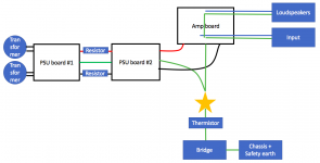
I redid the input and output as previous post suggested with huge improvement (still not 100 perfect).
I haven't put in the thermistors in series with the two star grounds. Would you suggest doing that?
The attached image is pretty blurry, i hope it still shows what i wanted to illustrate.
The changes is highlighted with the black marker pen.
The only parts that are hidden are the return routes for the signal current and the speaker current. Are they connected on the amp PCB?
If so, then the "star" you still have off board, should be moved on board, i.e. the Power Zero Volts goes straight to the PCB not via a remote star.
If they are not connected on the PCB, then these two routes should follow the signals back to a common reference point/voltage. This is the off board "star"
The star whether it is on board or off board is your main audio ground. It is the voltage reference that ties the input to the output. But it must not be remote, it must not create excessive loop areas in any of the current routes.
Now that you have a quiet amp, draw what you have completed. colour in the current flow and return routes for every circuit. Are they all close coupled?
that group of 4 points does not need to be coincident. It can be a bus bar and work well.speaker gnd goes from amp pcb
each PSU having own NTC or bridge combo , going from main GND point to chassis safety GND
A pair of amplifiers inside a common metal enclosure can never be a mono block.No, i cannot get a true star ground for the caps since they are fitted to PSU boards. I thought i could get more of a star ground by routing both boards to star ground. But if i understand from Andrews last post, iäd be better of by connecting the boards together and then to star ground.
I will adding the two NTCs to Earth/Safety and see what it provides.
Wouldnt two different mono blocks be true mono if they dont have the ground loop breaker?
The best that can be achieved is a dual mono where the two channels are isolated from each other.
Isolated in this context means NOT connected.
As ZenM says in post14, for a dual mono you NEED two separate Chassis connections to satisfy the SAFETY requirement:
all exposed conductive parts should be connected to the protected chassis.
But this requires TWO isolated dual polarity PSUs. You do not connect the channels together.
A pair of amplifiers inside a common metal enclosure can never be a mono block.
The best that can be achieved is a dual mono where the two channels are isolated from each other.
Isolated in this context means NOT connected.
As ZenM says in post14, for a dual mono you NEED two separate Chassis connections to satisfy the SAFETY requirement:
all exposed conductive parts should be connected to the protected chassis.
But this requires TWO isolated dual polarity PSUs. You do not connect the channels together.
I agree, "dual mono" isn't a pair of mono blocks. Depending on where you want to draw the line regarding the word mono one amplifier could be more or less separated. Mine share mains connector, soft start and chassis. Other than that, it's built with separate components.
from functionality side , dual mono or mono blocks - just semantics
I dare to say , when normal power range is in question (say up to 50-75W/ch) , even IEC connector and starting mains routing inside the case can be shared between channels , without compromising anything (though - each xformer must have own fuse)
from physical/cosmetic side , there is fat difference between mono blocks and dual mono
This new diagram is much better.
The only parts that are hidden are the return routes for the signal current and the speaker current. Are they connected on the amp PCB?
If so, then the "star" you still have off board, should be moved on board, i.e. the Power Zero Volts goes straight to the PCB not via a remote star.
If they are not connected on the PCB, then these two routes should follow the signals back to a common reference point/voltage. This is the off board "star"
The star whether it is on board or off board is your main audio ground. It is the voltage reference that ties the input to the output. But it must not be remote, it must not create excessive loop areas in any of the current routes.
Now that you have a quiet amp, draw what you have completed. colour in the current flow and return routes for every circuit. Are they all close coupled?
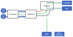
This is how it looks now.
The star ground is close to the PSU.
Attachments
This is how it looks now.
The star ground is close to the PSU.
Cables from PSU to amplifier board is not as.far apart as the picture make it look.
Just build this twice for two mono channels. Not clear about how you wired the bridge and thermistor. Normally a bridge rectifier with 10ohm resistor plus capacitor are used or just a thermistor on it own.
See how the STAR has moved to the amp board.
See how the STAR has moved to the amp board.
Attachments
Just build this twice for two mono channels. Not clear about how you wired the bridge and thermistor. Normally a bridge rectifier with 10ohm resistor plus capacitor are used or just a thermistor on it own.
See how the STAR has moved to the amp board.
Unfortunately, as previous described. Connecting both channels via earth caused hum. The thermistors probably made a difference even though I tried it at the same time as I re-routed the first psu board ground
I find this a clear summary of the grounding issues and the diagram on page 21 shows a very effective way to wire practically http://hifisonix.com/wordpress/wp-c...re-up-a-Power-Amplifier_Updated-Autosaved.pdf
I find this a clear summary of the grounding issues and the diagram on page 21 shows a very effective way to wire practically http://hifisonix.com/wordpress/wp-c...re-up-a-Power-Amplifier_Updated-Autosaved.pdf
Thanks! I haven't rread that paper before. Other than that, I've tried to read all I'd come across regarding this.
At first glance it looks like the new topology in my amplifier
Unfortunately, as previous described. Connecting both channels via earth caused hum. The thermistors probably made a difference even though I tried it at the same time as I re-routed the first psu board ground
That is because you need a bridge/thermistor per channel. Making your amp safe is the first priority.
Perhaps drawing both of the channels will help understand the problem.
Last edited:
the star should be located to minimise the LOOP AREA of the circuits that circulate current into and out of that star.This is how it looks now.
The star ground is close to the PSU.
This requires the star to be on the PSU to AMP twisted triplet.
When you go to a stereo build you will find it is better to have the star very close to both channel amplifier PCBs.
In a mono block build the star ends up ON the Amp PCB.
If you have two isolated channels, you must use TWO Disconnecting Networks to make the SAFETY connection from MAG to Chassis.Unfortunately, as previous described. Connecting both channels via earth caused hum. The thermistors probably made a difference even though I tried it at the same time as I re-routed the first psu board ground
If you have two connected channels that share a Power Zero Volts (single centre tapped secondary transformer + single bridge recifier), you can only use a single Disconnecting Network.
Have you read D.Joffe? His paper is posted many times on this Forum.
It explains why a two channel amplifier inside a common metal chassis will hum due to interference circulating around inadvertant loops in the build/assembly. This applies just as much to a stereo common Zero Volts build as it does to a Dual Mono Build/assembly.
If you have two isolated channels, you must use TWO Disconnecting Networks to make the SAFETY connection from MAG to Chassis.
If you have two connected channels that share a Power Zero Volts (single centre tapped secondary transformer + single bridge recifier), you can only use a single Disconnecting Network.
Have you read D.Joffe? His paper is posted many times on this Forum.
It explains why a two channel amplifier inside a common metal chassis will hum due to interference circulating around inadvertant loops in the build/assembly. This applies just as much to a stereo common Zero Volts build as it does to a Dual Mono Build/assembly.
I don't think I've came across that article (yet) but I'll look for it now you talked about it.
I'll move the amps reference onto the psu pcb.
Could you just please explain the acronym MAG?
I think I found the paper.
Also I moved the reference point for the amp to the psu pcb. It got even more silent than before. Now there's no hum or any other sound what so ever while the music isn't playing. I even think the transformers sound less.
Also I moved the reference point for the amp to the psu pcb. It got even more silent than before. Now there's no hum or any other sound what so ever while the music isn't playing. I even think the transformers sound less.
from post21I don't think I've came across that article (yet) but I'll look for it now you talked about it.
I'll move the amps reference onto the psu pcb.
Could you just please explain the acronym MAG?
The star whether it is on board or off board is your main audio ground. It is the voltage reference that ties the input to the output.
I hadn't seen that paper before either, so it's worth posting the link (no doubt yet again).
http://www.updatemydynaco.com/documents/GroundingProblemsRev1p4.pdf
Cheers,
Jeff.
http://www.updatemydynaco.com/documents/GroundingProblemsRev1p4.pdf
Cheers,
Jeff.
- Status
- Not open for further replies.
- Home
- Amplifiers
- Pass Labs
- F5 Turbo v2 - Hum problem