bypass tone controls in feedback network
Good day good people.
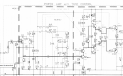
I've got a Yamaha integrated amplifier with an odd tone circuit built in the feedback network shown in the schematics below.
What i would like to know, if you can help me, is what would be the best approach to remove the tone circuit maintaining the overall characteristics of the amp? Another member of the forum suggested shorting TL1 and TL2 (and removing connections to the tone board) and removing R159 but i'm still not sure that it would not disrupt the normal function of the circuit.
And also would be cool to learn about it.
I'm really not worried in maintaining the amp as original because i got other very good amps, and this was a beaten up dumpster salvage that i already modded the crap out of it in many ways with pretty good and unexpected results. Also i'm using it as a learning platform.
thank you very much.
Good day good people.
I've got a Yamaha integrated amplifier with an odd tone circuit built in the feedback network shown in the schematics below.
What i would like to know, if you can help me, is what would be the best approach to remove the tone circuit maintaining the overall characteristics of the amp? Another member of the forum suggested shorting TL1 and TL2 (and removing connections to the tone board) and removing R159 but i'm still not sure that it would not disrupt the normal function of the circuit.
And also would be cool to learn about it.
I'm really not worried in maintaining the amp as original because i got other very good amps, and this was a beaten up dumpster salvage that i already modded the crap out of it in many ways with pretty good and unexpected results. Also i'm using it as a learning platform.
thank you very much.
Attachments
Last edited:
Here is what I would do...
1/ Measure the gain of the power amp with tone controls centred. Don't have speakers connected for this, it would be to loud. Use a 1kHz sine test tone and using a scope (or good DVM) measure the AC voltage on C129 and also on the speaker output.
Calculate the voltage gain by dividing one into the other.
2/ Calculate a new value for a suitable feedback resistor based on the gain calculated and the fixed value of R157
3/ Remove C143 and C145 which will isolate the tone section.
4/ Remove R159
5/ Link TL1 and TL2
6/ Fit the newly calculated feedback resistor in place of R159
I have a decent DVM. Will it do with a pc generating 1khz connected on the input? The amp has no electronics in the signal before C129, only source switches. You said it would be loud with the speakers connected, so do i have to put max volume?
can you tell me the formula to calculate R157 based on the gain?
thank you
can you tell me the formula to calculate R157 based on the gain?
thank you
The signal used must be a sinewave and you need the volume loud enough to be able to get a reliable reading for the smaller input voltage.
For example.
14Vrms measured on output.
1.13Vrms measured on input.
Gain = 12.3
New feedback resistor = 1800 multiplied by the gain minus 1800
(1800*12.3)-1800 = 20340. We would use 20k or 22k for R155.
R157 always remains at 1800 ohm.
I can see another minor complication... the total resistance of R145 and R147 should ideally add up to the value of the feedback resistor. Having them different could a small DC offset. It would be worth checking the DC offset before and after. Anything below around -/+ 100mv is acceptable.
ok. i get it.
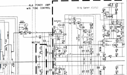
If it helps in solving the mistery i found schematics for the Yamaha AX500 which has tone bypass in a similar circuit... Altough i would prefer to short the circuit at TL1 and TL2 but i lack the ability in circuit analysis to extrapolate from the AX500 schematics.
If it helps in solving the mistery i found schematics for the Yamaha AX500 which has tone bypass in a similar circuit... Altough i would prefer to short the circuit at TL1 and TL2 but i lack the ability in circuit analysis to extrapolate from the AX500 schematics.
Attachments
Last edited:
I woulld make it even simpler:
1) remove C143/145
2) bridge Tl1 to Tl2
3) gain will now be (39k/1k8)+1=22.7 X , which is FINE for a power amp.
I´d hesitate to make gain lower than that since this amp does not have a real preamp.
That said, I´d simply set Bass and Treble pots halfway, flat, and forget them ... until actually needed which will happen sooner or later 🙂
And maintain R159? I'm a bit confused as Mooly said to replace R159 on is first post but on his second post he only talks about changing R155 and doesn't mention R159...
I have a separate digital EQ in the source, so right now i would like to temporary remove them and listen and measure the amp without them as i found a weird skew in frequency response plot that may be caused by the controls. Also i really don't care about them.
I have a separate digital EQ in the source, so right now i would like to temporary remove them and listen and measure the amp without them as i found a weird skew in frequency response plot that may be caused by the controls. Also i really don't care about them.
Once you short Tl1 to Tl2 R159 becomes irrelevant, you may leave or pull it.And maintain R159? I'm a bit confused as Mooly said to replace R159 on is first post but on his second post he only talks about changing R155 and doesn't mention R159...
I have a separate digital EQ in the source, so right now i would like to temporary remove them and listen and measure the amp without them as i found a weird skew in frequency response plot that may be caused by the controls. Also i really don't care about them.
For peace of mind, I´d leave it.
It does NOT influence negative feedback/(gain/frequency response since it goes from amp output rail (speaker out) towards the input differential pair, but is audio *grounded* by C139 .
I bet its original function was to provide a stable DC path for the input differential pair without depending on tone control wiper contacts, which might eventually become scratchy; now since you are removing them from the path and leaving R155 directly connected to output rail, it´s not needed.
Leave it, it will contribute a tiny amount of current to slightly reduce offset ... we are talking a couple mV here.
In my first post, this:
should have read R157 and not R159.
It gets difficult because I keep scrolling up and down the page to see the circuit... sorry 🙂
In the original circuit R159 is needed for DC feedback because R155 is AC coupled via the tone network.
All you are doing is replacing R155 with a value that gives you the same gain as you have now (that's why we calculate a new value). R159 is removed because R155 now provides both AC and DC feedback when TL1 and TL2 are shorted.
For minimum offset R155 should ideally equal the combined value of R145 and R147.
6/ Fit the newly calculated feedback resistor in place of R159
should have read R157 and not R159.
It gets difficult because I keep scrolling up and down the page to see the circuit... sorry 🙂
In the original circuit R159 is needed for DC feedback because R155 is AC coupled via the tone network.
All you are doing is replacing R155 with a value that gives you the same gain as you have now (that's why we calculate a new value). R159 is removed because R155 now provides both AC and DC feedback when TL1 and TL2 are shorted.
For minimum offset R155 should ideally equal the combined value of R145 and R147.
So i'll try R155=49Kohm (R145+R147 based on Mooly's advice), short TL1 and TL2, remove C143 and C145 and R159 (or leave R159 for peace of mind like Fahey said).
Very cool. Thank you both very very much.
Very cool. Thank you both very very much.
If you leave R159 in place then it will be non optimal for DC balance because that resistor plus R157 will appear in parallel with R155. That could create a larger DC offset.
OK, already did the mod. Everything went smooth.
The only downside, which is not really a downside because it's easy to compensate with the volume knob, is that i lost 12db gain in the power amp. I'm using R155=47kohm (no 49kohm in the store).
The RMAA analyzer gave better results than i was expecting. I really coudn't be more happy with the results. IMDistortion went down, THD went down, noisefloor wentdown 3db, frequency response went ruler flat (i really suspected the tone controls were the culprits for skewing i was seeing in the graph before) and crosstalk went from 74db to 92db 😱.
I compared RMAA readings with exact same parameters except amplifier volume knob.
The only thing to do, maybe, is upping R155 from 47kohm to another value to compensate for loss of gain.
I got the formulas for gain based on resistors you gave me. How do i translate that for db? Or should i just be happy with the results and leave it based on rmaa readings?
Speakers DC offset went from 23mv/16mv (L/R) to 19mv/16mv.
So i won in everything but lost gain, but i think that's no drama.
The best thing is i cured the brightness i was hearing trough my speakers that got me plotting the freq. response with RMAA in the first place.
thank you for all your help.
Last edited:
Losing gain is a bit of a mystery thb.
You need to do a conventional measurement and look at Vout vs Vin and make sure it agrees with what we expect.
100mv rms at the input should give around 2.7 volts rms at the output. That gives a voltage gain of 27.
Calculated gain would be (47000/1800) + 1 which is 27
Gain in db is 20 log(Vout/Vin) which is 28db
Don't know if you saw it, but in the AX500 schematics in post #5, feedback signal still passes trough a 220k resistor before entering the input transistor pair, when tone bypass is engaged. Was wandering if it should be part of the calculation.
I could try larger resistors for R155 until i get the same db reading on RMAA analyzer, if that makes sense.
Oh, and i did remove R159.
Anyway the amp is sounding very good.
I could try larger resistors for R155 until i get the same db reading on RMAA analyzer, if that makes sense.
Oh, and i did remove R159.
Anyway the amp is sounding very good.
Last edited:
The 220k appears to be to provide a DC path to bias the two caps as the switch is operated.
You have to do a measurement to confirm the gain really is as we expect. If it is not then we need to look why.
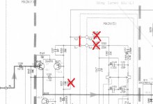
This is how your circuit should look. The gain is as mentioned above and is (R155/R157) + 1
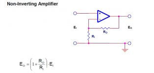
It is functionally the same as a basic non inverting opamp.
You have to do a measurement to confirm the gain really is as we expect. If it is not then we need to look why.
This is how your circuit should look. The gain is as mentioned above and is (R155/R157) + 1
It is functionally the same as a basic non inverting opamp.
Attachments
Ok. Will do the measurement. That circuit is exactly what i done with the exception of changing R155 to 49kohm and didn't need to remove C143 and C145 as removed the connection to the tone board altogether. I have double checked everything and will now triple check.
EDIT: Done the measurement. At 1V input, amp volume to max, i get 44v at speaker output, AC of course.
But if i reduce input level to 100mv, i read 16.2v on speaker output, amp on max volume.
At 400mv input i read 29.4v output.
Maybe i need a new DVM...
All done with 1khz tone from Sinegen on a pc.
My dac output has no dc offset, maybe because of precision opamp LME49720.
Last edited:
- Status
- Not open for further replies.
- Home
- Source & Line
- Analog Line Level
- tone controls in feedback network - the best approach