I mentioned the common output CCS, and considered its the cons / pros if the driver's CCs is already in place.
Sorry, can't provide the measurements, I mostly evaluated it by my ear,.. and I'm sharing just me ear experiences here.
So to recap: the common CCS in driver/first stage + the following separate CCSes in output stage seems to be the optimal for simple designs, as it proven by Baby Hue, El Cheapo, etc etc.
So, the two CCS's are set for equal currents so the OPT sees balanced DC.
Gents, another thought on a common cathode choke.I am not necessarily advocating this approach above a single CCS, but at least you now understand why it works. For me the ability to have an adjustment free amp far outweighs any theoretical drawbacks.
Make an informed decision based upon what works for you.
Shoog
Let's say we have enough of tubes supply and can get a closely matched quad, so the OPTs are balanced while the common CCS/chokes used. But there is still a nasty chance if a single tube of a pair is missing and the second one receives the double current with consequences. (this is for the case if e.g. some unaware end-user makes this mistake while rolling).
How about this: make the common choke with bifilar (or separate) windings for each shoulder. So they create the individual DC bias, but work commonly for the AC due to a common magnetic flux. Will this work?
Technically such the choke can be made of two smaller identical ones, with removing the stack of I-laminations and by combining two rests of E cores + coils together with an appropriate gap.
This is a good idea: DC resistances of each windings provide independent DC bias, while signal commonality of the choke is preserved.
It might be worth noting that choke does not behave as CCS with regard to DC current, so it will not force twice the current into a single tube.
It might be worth noting that choke does not behave as CCS with regard to DC current, so it will not force twice the current into a single tube.
It might be worth noting that choke does not behave as CCS with regard to DC current, so it will not force twice the current into a single tube.
That's the idea behind using a choke: to give the output stage of the Tabor amp more "flexibility". A solid state current source providing the output stage with a fixed DC current might cause the amplifier to clip less benign.
Last edited by a moderator:
Tnx, but what about the magnetic flux? I exactly assumed it still will force a bit of current into the second tube. Maybe not as much as if cathodes are common, around a half.This is a good idea: DC resistances of each windings provide independent DC bias, while signal commonality of the choke is preserved.
It might be worth noting that choke does not behave as CCS with regard to DC current, so it will not force twice the current into a single tube.
Consider it working similar as two independent CCSes with a cap bridged between cathodes. The size of the core here is same as the cap's capacity.
Not a problem. For DC, the windings are completely independent, and that is what matters. Magnetic flux changes affect only AC signal currents and voltages.
"Talk to each other" means that they will behave as one coil with regard to AC signal. In other words, two coil choke is same as regular one coil choke for AC, but two separate resistors for DC.
Guys, very intersting discussions...to be honest, I never used a choke as Anode load or even common cathode choke...sofar I used only mosfet based ccs from Kevin C. or Bd179/bc547c based like triodedick used in LTPs.
So, if I got it right, you suggest to replace the CCS in a LTP with a choke, right ?
So, I guess the bias of the two tubes would be set by the one resistance of the choke, assuming very well matched triodes, correct ? ...and I guess if the resistance of thechoke is not enough, you add simply a resistor in series ?
And this sounds best in your experience ?
I would think that the AC impedance is much lower than a real CCS, no ? Even with 22H I am hitting at 20hz only 2763 ohms...ok, if I would have only to fire a diff. pair of 6sn7 and take a ll1667, I have 270H with nearly 34000 ohms at 20Hz...this becomes serious..., at 200hz 340000 and at 2000 3400000.....
...so I guess Th. Mayer was using in his state of the art diff. linestage either two chokes in parallel or used one per leg of his 801A...I was always wondering, why he needed four ll1668: http://3.bp.blogspot.com/-f8pGkhCKS7o/Vg-ZBQhts3I/AAAAAAAAMUg/1dDRyqxCXa4/s1600/silverparts.jpg
Did anyone compare this to tube-CCS ? Even if they are in theory inferior, I could imagine that they sound better than silicon ? That at least what Allen Wright was stating if I remeber right ?
Last edited:
Choke instead of CCS as a long tail was just an interesting idea. I haven't yet seen any practical circuit using it.
You correctly point to choke's limitation - impractically high inductance required for reproducing low frequencies. However, there are at least three approaches to deal with it.
First, use of triodes with low Rp. For example, 6N6P with Rp=1.8 K at 30 mA, only 150 H (!) is required to make a tail of 10xRp at 20 Hz. One might argue that 150 H 60 mA choke is a pipe dream, but wait for the second point...
Second, use center-tapped choke, CT grounded and ends connected to LTP cathodes. Because DC magnetization is cancelled, ungapped core can be used, with 150 H per leg at 30 mA being a trivial inductance. Many PP output transformers will foot the bill.
Third, limit the bandwidth on the lower side. An amplifier with flat 20-20,000 response is a daunting and unnecessary task. Separate amplifiers for bass and mids+treble are much easier to design and naturally accommodate low and high frequency speaker drivers.
All correct.
Even though the AC impedance is much lower than the CCS' - I like the idea of building a PP Amp of almost all of Tubes and inductors. Well, a couple resistors might be necessary to load the driver and one more for the input grid leak.
Otherwise == the purist's dream!
We discussed such with Seavan diy member while my recent visiting him. With careful and proper components selection the amp comes not that expensive and not heavy with 10-15 Watts achieved. I think I will draw and scan the first take schematics.
Hmmm, Iwill try this out and yes, I got the point of the center-tapped version which is why I got some LL1668Am-PP some time ago...I am not sure though why Thomas did not use this approach and instead used four SE-Types ?
But maybe he didnot even used really a LTP...
Ok, back tothesubject: http://www.lundahl.se/wp-content/uploads/datasheets/1667_68.pdf ...where is the limitation ? So, first it offers 340ohm per winding which sounds like a good thing. And we have min. 100H when connected in series...so maybe we have 50H when used as PP.
My current linestage with LTP uses an 4P1L with 1.3K rp in triode. I am running it with 30mA, 175V, -11V Vg. So, if the Vg need now to be substracted as we have some kind of cathode bias over the choke, My new Vanode-cathode will be 165V, which is fine for it as well. Maybe -10V Vg is a good choice.
10Volt per tube Vg, with 340ohm per winding as Centertapped...gives 29.4mA...! Perfect ! Right ? It would be a quickthing to do...
...hmmm there is only one thing I need to consider: Right now my DAC (Ess9018) is directly connected to the grid and is having a positive DC-offset...something I have nothing to do with as the CCS has a negative voltage and just automatically adjusted the bias...not sure what happens when there is no CCS anymore...
Last edited:
sser2,
I was thinking again about theidea of the center-tapped-choke and havingthe cathodes connected at the end....
...is this really working ? In a LTP ? I mean we have per leg 340 ohm resistance using the ll1668 as an example plus for the AC the impedance of theinductance of each leg....between the two cathodes !!! While LTP per definition should be ONE cathode (two connected together) more or less, right ?
Well, this becomes than a challenge: In my example, I would need a 166Ohm SE choke with ideally more than 25H i guess...
Last edited:
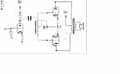
So, I’ve been thinking of something like this, nothing new, with slight additions to the schematics you can find in Internet:
The appropriate for the project tubes: 6EA7 / 6EM7, the Novars 6KY8A, 6LR8, 6GF7A, the Compactrons 6LU8, 6T9 and Pentodes 6AD10, 6T10, 6AL11, 6J10, 6Z10, otherwise the separate driver tubes.
With double pentodes the UL could be implemented on both stages.
Per the calculations for e.g. 6KY8A & 6AD10 the B+ would be 320-350V with 850-900 Ohm center-tapped cathode choke’s full resistance for the output stage.
Want to discuss 3 things:
- Due to low current of driver stage - would the common cathode choke be more beneficial?
- Should the driver stage be rather powered from B+ ?
- The interstage transformer’s secondaries - couple times I saw them connected rather straight to cathodes (red arrows). The thing is that with center-tapped choke the potential between cathodes can reach very high (in some source mentioned 170Vpp in case of KT-88 pair).
Your opinions welcomed.
An externally hosted image should be here but it was not working when we last tested it.
The appropriate for the project tubes: 6EA7 / 6EM7, the Novars 6KY8A, 6LR8, 6GF7A, the Compactrons 6LU8, 6T9 and Pentodes 6AD10, 6T10, 6AL11, 6J10, 6Z10, otherwise the separate driver tubes.
With double pentodes the UL could be implemented on both stages.
Per the calculations for e.g. 6KY8A & 6AD10 the B+ would be 320-350V with 850-900 Ohm center-tapped cathode choke’s full resistance for the output stage.
Want to discuss 3 things:
- Due to low current of driver stage - would the common cathode choke be more beneficial?
- Should the driver stage be rather powered from B+ ?
- The interstage transformer’s secondaries - couple times I saw them connected rather straight to cathodes (red arrows). The thing is that with center-tapped choke the potential between cathodes can reach very high (in some source mentioned 170Vpp in case of KT-88 pair).
Your opinions welcomed.
> Your opinions welcomed.
Very quickly: compute the gain.
If that 2nd stage cathode choke does anything at all, it eliminates all grid-plate gain in that stage.
Yes, the MacIntosh "looks-like" this, but the cathode winding is coupled with plate winding to load.
I'm also wondering about the gain of the 1st stage, windings coupled back to OT. Should be easy to estimate. Me, I'm for bed.
Did anyone compare this to tube-CCS ? Even if they are in theory inferior, I could imagine that they sound better than silicon ? That at least what Allen Wright was stating if I remeber right ?
You want the highest impedance sitting under the cathodes of a LTP for best performance. A choke is going to fall well short of what a CCS can do! (You can use a tube for the CCS too)
In your output stage, the choke's presence there will be a disaster for frequency response (more so than it would be for the driver), since you'll have different unbypassed AC impedance depending on frequency, therefore some variable local NFB, and consequently wonky frequency response.
Thanks PRR, as always, a spiced feedback.
I am not that advanced with tubes as e.g. .. with anything else ))
This is just a first take aka "what if. ..", in some future I'm going to just hook it all up and see where is wrong/right.
I thought about driver stage gain. Let's put it this way: what if instead of cathode chokes there are R or R+C. Do I get it any better with chokes? Well, not as good as with CCS, but from the purist's point of view (no silicone blasphemy in the Amp!!) this should go "kosher" ))
Unless I have misunderstood you, this CT choke will do the opposite of what you need. A PP OPT cancels DC magnetisation and applies a signal on one side in antiphase on the other side. For an LTP tail you want a signal on one side applied in phase on the other side. You could arrange a transfomer to do this, but then DC would add rather than cancel.sser2 said:Second, use center-tapped choke, CT grounded and ends connected to LTP cathodes. Because DC magnetization is cancelled, ungapped core can be used, with 150 H per leg at 30 mA being a trivial inductance. Many PP output transformers will foot the bill.
A choke is likely to provide worse performance than a CCS (narrower bandwidth, higher distortion, hum pickup). It will be bigger and heavier and more expensive. In what sense is this good engineering?
- Status
- Not open for further replies.
- Home
- Amplifiers
- Tubes / Valves
- Common Cathode Choke discussion