I got one channel up and running so that I was able to measure DC from the output. It was a quick and dirty setup with temporary sinking, but the DC was approx. -37 mV so quite promising. The next step is to cut some aluminum for a heatsink and finalize the wirings and casing. Too bad I don't have much time for building before the weekend. I just can't wait for the first listening of this beast!
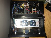
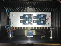
I attached some pics of the current status of my build. I'm re-using an old Modushop case that I had for a tube headphone amp, so the IEC socket, RCAs, vol. pot, headphone jack and power switch placements are pre-determined.
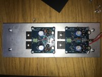
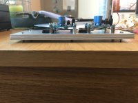
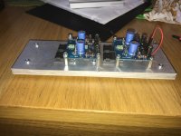
Yesterday I got the heatsink for lateral FETs almost ready. I built it from three 3 mm sheets of aluminum that are bolted together with heat transfer paste in between. I just had an unjused 3 mm aluminum plate lying that I wanted to utilize, so not the easiest way to do it but hopefully it'll work.
I'm planning to bolt the lat FETs to the sink with silicone pads as isolators before I adjust the output DC. I'll let it heat up for 30 min first and then do the measurements so the temperatures are hopefully settled and corresponding the normal use conditions.
You can also see the Nazar regulators that are installed vertically to the black heatsink. I'm hoping the heatsink will act as a magnetical shield too for the transformer in the back side of the case. Lots of wirings and minor tweakings left to do before finished, but it's getting there.
Attachments
Why not turn the PCB 90° so that the input is facing the ALPS, and the laterals to the heatsink.
You will then have a short distance from ALPS to input.
Output is low impedance.
Patrick
You will then have a short distance from ALPS to input.
Output is low impedance.
Patrick
Yes, I had thought about that possibility too, but then I decided that it is better to have the laterals in the middle of the alu bar for better heat dissipation. If rotated 90 degrees the laterals would be on the top side of the alu bar. I don't know yet if this matters at all, but if I get hum then I'll definately try it. Now the PCBs are already bolted to the sink and it would be quite a lot of work to re-do them.
Just get it working and playing music first.
It does not have to be its final configuration as is.
Part of the fun, the fine tuning of layout, wiring, ...., etc.
Patrick
It does not have to be its final configuration as is.
Part of the fun, the fine tuning of layout, wiring, ...., etc.
Patrick
Ok, what did I do wrong now? 🙂
I let the circuit run with only one channel connected for about 30 min and I measured the output DC offset that was 48 mV. I wondered why the sink was so darn hot and I measured the temp. Wow, 55 C at the coolest point and the laterals were 65-70 C. And only one channel running.
Then I measured how much current was my circuit drawing: 230 mA per polarity! After that I checked the Vgs of both laterals: N-channel 0,62 V and P-channel 1,00 V. That means I have approx. 180-190 mA bias, if I'm not mistaken by my earlier measurement results.
So I think I should reduce the bias by altering the R21 and R22 values, but I'm just not quite sure how can I calculate the values beforehand?
Anyhow I think my sinking is not sufficient and I need more of it.
> Anyhow I think my sinking is not sufficient and I need more of it.
That is certainly the case. A drift from 190mA to 230mA for 70°C is what I consider reasonable.
The whole circuit will heat up, which means that the Idss of the JFETs etc will also drift.
But I would still check whether there is oscillation with your Nazar regulators.
Suppose you design for 250mA thermally, with +/-24V rails, you will have 12W to dissipate, per channel.
You probably will also have the same amount of heat to dissipate with the Nazar (which is a shunt and not a series reg).
So you would need a heatsink of ~ 1W/°C.
And a reasonable size would be 200x50x40mm, again per channel.
https://www.reichelt.de/Profilkuehl...Mf9833f363c6a6179fb29aaa07fd1aa7f&LANGUAGE=EN
Patrick
Last edited:
A 2109 case would be minimum :
Full aluminum chassis Power supply box Power amp Enclosure PSU 211*90*257mm GE | eBay
Patrick
Full aluminum chassis Power supply box Power amp Enclosure PSU 211*90*257mm GE | eBay
Patrick
Jeah, I had calculated the loads and dissipation for only one voltage polarity. Somehow I didn't realize that the given current draw of 170 mA per board was for both polarities, so there's twice as much loading. 😱 Oh well, you live and learn. 😀 Time to look for a new chassis then, thanks for the link.
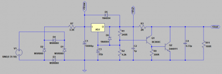
I believe my Nazar regs will need a bit of tweaking too, as you suspected. Now the circuit is like in the attached picture. It's your design, by the way, and I found the .asc files from somewhere in this forum. I think I'll need to change the value of R3 from 2 ohm to about 1.5 ohm, if my simulations are correct. Though I'm not sure how to make sure it doesn't oscillate?
I believe my Nazar regs will need a bit of tweaking too, as you suspected. Now the circuit is like in the attached picture. It's your design, by the way, and I found the .asc files from somewhere in this forum. I think I'll need to change the value of R3 from 2 ohm to about 1.5 ohm, if my simulations are correct. Though I'm not sure how to make sure it doesn't oscillate?
Attachments
a) The design originates from Mr. Nazar, not me.
b) There is no guarantee that every regulator is stable with every amplifier circuit.
I always test me amps with some simple PSU, first with a lab supply, then maybe 317/337.
If the temperature is significantly different with another regulator, then you for sure have oscillation.
And of course you will see it at the output with a scope, even with shorted inputs.
Patrick
a) I know it's originally designed by Mr. Nazar, but you had made a version of it and kindly provided the LT Spice file, so it was easy to try it.
b) At least my Nazar regs have drawn the same amount of power (~20W) from the 230 VAC mains according to my el cheapo energy consumption meter even if I had a resistor loading the regs or the UTHAiM board. I don't know if that's any indication or not? Unfortunately I don't own a scope so it's hard to verify. I've been looking for this though: https://www.google.fi/url?sa=t&rct=...0.html&usg=AFQjCNGlrOKhjb4HlJRCeaP2M7KyozZGPg It would be an affordable solution, if it's any good...
I just ordered a new chassis from eBay according to EUVL's hint: 2109 silver front pass chassis full Aluminum Preamplifier enclosure PSU case
It's a real PASS approved case. 😉 I hope I can scrub the logo off or then I'll have to place a sticker on top of it.
> I just ordered a new chassis from eBay according to EUVL's hint
No Sir, not my hint.
I never endorse such copies that violates someone else's trademark.
The one I linked to in reply #68 is just a blank case with no logos, etc.
And it is located already in the EU, so no further import duties.
Patrick
No Sir, not my hint.
I never endorse such copies that violates someone else's trademark.
The one I linked to in reply #68 is just a blank case with no logos, etc.
And it is located already in the EU, so no further import duties.
Patrick
Yes. I meant no offence and I too am against trademark violations. Like I said, I'm going to scrub the logo off or cover it with something. My bad that I put the link here, maybe a forum admin can remove it. I was just looking for an adequately heat sinked case that requires minimum amount of machining for me because of my insufficient metal processing tools. Unfortunately I could not find one within EU for a price I can afford. At least the sinks in the enclosure match the one you tipped me of.
I always test me amps with some simple PSU, first with a lab supply, then maybe 317/337.
If the temperature is significantly different with another regulator, then you for sure have oscillation.
And of course you will see it at the output with a scope, even with shorted inputs.
Patrick
Today I hooked up one UTHAiM board with a LM1086 based dual power supply set to +- 24V. The current draw is the same 0,23 A then with my Nazar reg. So I suppose the Nazar is not oscillating.
This time I let the circuit be on power for only max. 5 min at a time. Still the Vgs values measured from the lateral FET pins were 0,628 V (n-channel) and 1,01 V (p-channel) even at the start-up before things get hot. If this is the correct way to indirectly measure the bias then I think it's running quite high bias 180-190mA.
In any case I will repeat these measurements when I get the properly heat sinked case and see if the bias is still on the high side.
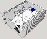
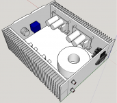
While waiting for my case to arrive I have made a simplified 3D model of it with Sketch-up. In the first picture you can see the UTHAiM boards placed on the side heat sink. I think I'm going to rotate them 90 degrees counter-clockwise in order to get the lateral FETs more in the middle of the sink. Also that way the inputs would be closer to the Alps pot and a bit further away from the trafo.
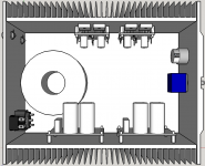
The second pic is a top side view and the third pic shows the Nazar regs placed on the other side sink.
I'm a bit worried about the input RCA connectors being so close to the trafo. Maybe I should use some trafo shield.
Any comments and improvements are welcome.
The second pic is a top side view and the third pic shows the Nazar regs placed on the other side sink.
I'm a bit worried about the input RCA connectors being so close to the trafo. Maybe I should use some trafo shield.
Any comments and improvements are welcome.
Attachments
The FET will have no problems with 200mA bias.
But you can lower it by reducing the biasing resistor values.
Patrick
But you can lower it by reducing the biasing resistor values.
Patrick
Good news for me at last. My UTHAiM is finally putting out some music! I had a quick and dirty test run after adjusting the output DC close to 0 V. Heatsinks are at 42 C degrees after one hour and the bias is quite high but I decided not to adjust it down since the amp seems to be working just fine. By the way, what's the expected power output @70ohm load with 180 mA bias?
Especially the Finnish band Kingston Wall - Shine On Me is sounding exceptionally good. 😉
Still a lot of wirings and aluminum grinding to do, but I'm very happy that the amp board itself is working.
Especially the Finnish band Kingston Wall - Shine On Me is sounding exceptionally good. 😉
Still a lot of wirings and aluminum grinding to do, but I'm very happy that the amp board itself is working.
Class A maximum output current at 180mA bias is >360mA.
At 70 ohm, you are voltage limited (to ~ +/-15V).
Which in turn corresponds to ~ 1.6W for sine waves.
For 16 ohm, you will be current limited at ~1W.
For 600 ohm, ~ 0.18W.
Patrick
At 70 ohm, you are voltage limited (to ~ +/-15V).
Which in turn corresponds to ~ 1.6W for sine waves.
For 16 ohm, you will be current limited at ~1W.
For 600 ohm, ~ 0.18W.
Patrick
 Thanks a lot!
- Home
- Amplifiers
- Headphone Systems
- UTHAiM -- Just for Fun