Costis, the news is that, running a very close second in current designs, is the very well behaved and "tame" MJL21194 that is also the preferred output device for circlophone. What the MJL21194 can give you that's better than 2SC5200, is a more placid tone and higher linear output power. The 2SC5200 may do better because of lower device noise when also used in low bias Class B designs; but, that is simply not applicable here with the Class AA amplifier and hot drivers. Rather than complicate the output, it may be a great deal more fun to complicate the driver, vas and input selection.
So, I'm saying that you probably don't want to bottleneck your Class A and Class AA designs with weaker high speed output devices and their less pleasant, less linear tone.
So, I'm saying that you probably don't want to bottleneck your Class A and Class AA designs with weaker high speed output devices and their less pleasant, less linear tone.
Costis, the news is that, running a very close second in current designs, is the very well behaved and "tame" MJL21194 that is also the preferred output device for circlophone. What the MJL21194 can give you that's better than 2SC5200, is a more placid tone and higher linear output power. The 2SC5200 may do better because of lower device noise when also used in low bias Class B designs; but, that is simply not applicable here with the Class AA amplifier and hot drivers. Rather than complicate the output, it may be a great deal more fun to complicate the driver, vas and input selection.
So, I'm saying that you probably don't want to bottleneck your Class A and Class AA designs with weaker high speed output devices and their less pleasant, less linear tone.
Thank you for the insight, I will try to explain my choice.
The criterion is current gain linearity. To me linearity is something we need in linear applications. There is no such thing as too much linearity.How can a less linear device can give higher linear output power, as you say?
I ordered them because I found them cheap online, but it takes some time to get here from Singapore, while if I want to get BD249C's I can get them cheap from the corner store. (the voices tell me not to use MJ series 😱)
The only thing I don't like (conceptually) about using fast BJT's as outputs is the "band aid" capacitors. I think it is better to have this cap embedded in a device (i.e. a slow output device). Opinion on this?
Ok I have been reading about this amp for a couple of days now. I am looking for boards most likely for the original circuit are there any available? I do not plan on making my own. Has anyone had some made and how would I do the same? Any info would be helpful. BTW, MJ21194's(2) can support up to how much power into 4 ohms?
As I said, there is no "official" board available, even if some members produced a number for their own use and gave out the surplus.Ok I have been reading about this amp for a couple of days now. I am looking for boards most likely for the original circuit are there any available? I do not plan on making my own. Has anyone had some made and how would I do the same? Any info would be helpful. BTW, MJ21194's(2) can support up to how much power into 4 ohms?
If you're intent on extracting the last (safe) watt from a pair of MJ21194, that could amount to 200W/channel. Good cooling mandatory
Has anyone by chance developed gerbers for this to be produced from the board manufactures for any of the different versions?
Mickey Moose (and a few other members) did it, If you offer him some compensation I am sure he will give you his files...Has anyone by chance developed gerbers for this to be produced from the board manufactures for any of the different versions?
From post#1Ok I have been reading about this amp for a couple of days now. I am looking for boards most likely for the original circuit are there any available? I do not plan on making my own. Has anyone had some made and how would I do the same? Any info would be helpful. BTW, MJ21194's(2) can support up to how much power into 4 ohms?
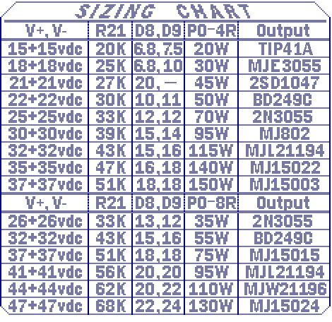
http://www.diyaudio.com/forums/atta...ories-beginner-friendly-circlo-size-chart.gif
That's a whole chart of examples. Looking at the list to a similar all-metal case device (MJ15022), that is 140W. Those output power figures are probably at a conservative THD%, so if pushed there could be somewhat more power available than listed on the chart.
Large list of boards, most with board (albeit not so much gerber), at Post#1. http://www.diyaudio.com/forums/soli...ccessories-beginner-friendly.html#post2968086Has anyone by chance developed gerbers for this to be produced from the board manufactures for any of the different versions?
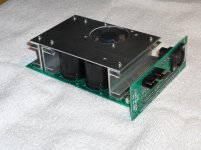
5 Circlophones in a biamped setup
Hello Folks,
After reading lot about Elvee's Circlophone , decided to replace my existing chipamp set up (LM3886 and TDA7294) with 5 Circlophones ( stereo for mid range and tweeter , mono for subwoofer )
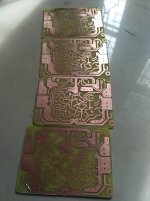
I am using Alex's pcb ( slightly modified to take 470pf cap).
Power supply : 20-0-20 AC 200VA transformer -1 each for midrange-tweeter and Sub
Simple 10000uf per rail PS capacitors .
Single PS is used for both the channels
Output -Cdil 2N3055HV6- (cdil is an Indian semiconductor manufacturer )
Drivers- Cidil BD140
VAS- Cdil 2n3019
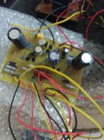
First connected mains bulb tester - Pass
Voltage across R8- 193mv
voltage across R11- 123mv (is this normal ?)
?)
Since these voltage looked fine as per the folks who have built it, connected test speaker , it sounds really good (as anyone who tried Circlophone ) - Not yet connected to biamped set up. I am sure its full capabilities will come to light then.
After half an hour of listening
2n3019s--- slightly warm- comfortable to touch
BD140-- Slightly warm- comfortable to touch
2N3055- much warmer than above 2 - can touch , but not very comfortable
One thing is bit strange :- i can hear faint hum when I place my ear close(3 inch) to speaker and also there is on off pop.
My suspect list
1) Output and other transistors are of bad quality
2) I am missing something related to ground (you can consider me as inexperienced )
3) Ceramic caps used for all the pF values
4) Power supply capacitors are insufficient
In spite of that small glitch , amp is fantastic, thanks to 'Elvee the genius' for sharing it and Alex for easy go PCB. Last but not the least, thanks to Daniel for clear documentation.
Hello Folks,
After reading lot about Elvee's Circlophone , decided to replace my existing chipamp set up (LM3886 and TDA7294) with 5 Circlophones ( stereo for mid range and tweeter , mono for subwoofer )
I am using Alex's pcb ( slightly modified to take 470pf cap).
Power supply : 20-0-20 AC 200VA transformer -1 each for midrange-tweeter and Sub
Simple 10000uf per rail PS capacitors .
Single PS is used for both the channels
Output -Cdil 2N3055HV6- (cdil is an Indian semiconductor manufacturer )
Drivers- Cidil BD140
VAS- Cdil 2n3019
First connected mains bulb tester - Pass
Voltage across R8- 193mv
voltage across R11- 123mv (is this normal
?)Since these voltage looked fine as per the folks who have built it, connected test speaker , it sounds really good (as anyone who tried Circlophone ) - Not yet connected to biamped set up. I am sure its full capabilities will come to light then.
After half an hour of listening
2n3019s--- slightly warm- comfortable to touch
BD140-- Slightly warm- comfortable to touch
2N3055- much warmer than above 2 - can touch , but not very comfortable
One thing is bit strange :- i can hear faint hum when I place my ear close(3 inch) to speaker and also there is on off pop.
My suspect list
1) Output and other transistors are of bad quality
2) I am missing something related to ground (you can consider me as inexperienced )
3) Ceramic caps used for all the pF values
4) Power supply capacitors are insufficient
In spite of that small glitch , amp is fantastic, thanks to 'Elvee the genius' for sharing it and Alex for easy go PCB. Last but not the least, thanks to Daniel for clear documentation.
Attachments

In isolation, these voltages are normal (maybe the voltage across R11 is marginally higher than usual, but nothing to worry about), but the voltage across R11 should be very nearly the half of R8 (it should even be slightly smaller than that in fact).Voltage across R8- 193mv
voltage across R11- 123mv (is this normal
If this was measured with a load, it could be an offset issue. Did you measure it?
The quiescent dissipation in each 3055 is ~6W, and if their heatsink is not very large, the temperature rise could be significantAfter half an hour of listening
2n3019s--- slightly warm- comfortable to touch
BD140-- Slightly warm- comfortable to touch
2N3055- much warmer than above 2 - can touch , but not very comfortable
1)Unlikely, not consistent with the symptomsOne thing is bit strange :- i can hear faint hum when I place my ear close(3 inch) to speaker and also there is on off pop.
My suspect list
1) Output and other transistors are of bad quality
2) I am missing something related to ground (you can consider me as inexperienced )
3) Ceramic caps used for all the pF values
4) Power supply capacitors are insufficient
2)Highly likely
3)No
4)They would need to be really small to cause that
Ok... now measured voltage after connecting 8 ohms load.
R8- 183mv- R11-90mv. Wow 🙂
placed all the amplifier boards inside enclosure. connected PS ground to metal enclosure , faint hum which was there in test set up, vanished into thin air so as on off pop -( You were Spot on sir Elvee ) .
Connected the entire system to 3 way active crossover and speakers and turned on the switch--- wow! 250 watts of pure bliss started filling the entire room .
I listen to lot of Indian classical music , those vocals were so clear that its only limited by source and recording techniques .
Since it is Elvee's cheap circlophone , I want to mention details of the expenses incurred on each circlophone.
1)Output - 2N3055- authentic CDIL- 42rs X 2 = 84Rs
2) Drivers -BD140- authentic CDIL- 9rs X 2= 18Rs
3) VAS-2n3019-vendor claim its authentic CDIL- 18rs X 2= 36Rs
4) schottky diode- 35rs X 2= 70 Rs
5) BC556B Fairchild - 8rs X 5= 40Rs
6) KC1845 Fairchild 12X 2= 24Rs
7) Other passive components are not even worth mentioning, hence rounding off at 50rs
8) PCB plus etchant - approximately -50Rs
Total = 372rs = Approximately 6USD !!
I think circlophone qualifies for one of the best amp design -- least complexity- as easy as making chipamp, it wont complain even if you give cheapest output transistor , and the most significant part is fantastic sound quality which is only limited by recording techniques and source (purely personal opinion and subjective )
Thank you very much Elvee !
Regards
Goutham
Very glad to oblige, and congratulations for your success!Thank you very much Elvee !
Gooday all.
I need some assistance please. I intend to build the circlophone and have a few questions.I have passed through the thread and should not have problems but just a few questions please.
I will be using a transformer which is +-50VDC.
The output transistors which I have in this voltage range are.( old stuff but still new)RCA
1.2n4348
2.2n3773
3. IRFP 240
4. IRFP250
5. IRFP460
The oldish drivers I have on hand are.
1. 2n3053
2. BFY 43
3. 2n5109
4. 2n1893
5. BFX34
It will not be a problem to get other drivers if needed.
The small transistors I have about all.
The speakers will be predominately 8 Ohm so I will build it for 4 Ohm, you never know.🙂
Which build can you guy's suggest. The BJT or Fet version. ( Single side PDF for DIY PCB please)
Thanks for your time !!🙂
Regards
Jan
The 2N3773/4348 have been proven to work, but they are not exactly fast.
In the Circlophone, they can manage the full audio range, but they would be better suited for Sub applications.
The MOSfets have been tested and they work (in their dedicated version, see the thread), but they will waste some of the positive excursion, leading to a diminished swing, and as a consequence output power.
The builder(s) seemed happy enough with it, but that's something you have to know and consider beforehand.
In the drivers, the 5109 has a too low Vce, the BFX34 too large capacitances.
This leaves the BFY43 and the 1893: both should work moderately well
Thanks for the reply Elvee. With a rail voltage of +-50vdc, What is the ideal VCE of the drivers and the capacitance ? I have no problem of getting better components. Can you plse state which modern components would be the best.I believe more watts give a better headroom.🙂
BF458/9 is perfectly OK, and easy to source. MJE340 is OK too.
Ideal collector capacitance is about 8pF +/4pF.
Heaps of 2SC's are also suitable, but I don't know them in detail, other builders have used some successfully, browse through previous builds
Ideal collector capacitance is about 8pF +/4pF.
Heaps of 2SC's are also suitable, but I don't know them in detail, other builders have used some successfully, browse through previous builds
- Home
- Amplifiers
- Solid State
- Building Elvee's Circlophone: Documentation, Parts, Accessories, & beginner friendly