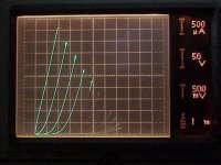
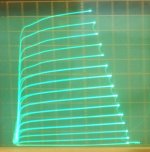
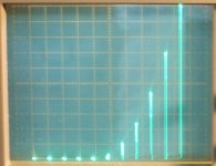
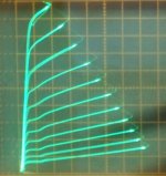
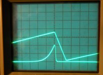
For those that want to photograph a Tektronix curve tracer, you can run into problems. The display rep-rate is dependent on the number of steps selected. If your camera can not do a long exposure (like mine), some of the steps will start to fade out. Below are the curves of a 12AX7 from a 576. There are versions of the 577 that have a bistable storage CRT which wouldn't be a problem.
Attachments
For those that want to photograph a Tektronix curve tracer, you can run into problems. The display rep-rate is dependent on the number of steps selected. If your camera can not do a long exposure (like mine), some of the steps will start to fade out. Below are the curves of a 12AX7 from a 576. There are versions of the 577 that have a bistable storage CRT which wouldn't be a problem.
Use the "Video" setting on your digital camera.
You can fashion a hood from foam-core board which will remove distractions -- but paint the internal part black. This would be akin to the Polaroid setup which Tek sold.
Use the "Video" setting on your digital camera.
You can fashion a hood from foam-core board which will remove distractions -- but paint the internal part black. This would be akin to the Polaroid setup which Tek sold.
I've been shopping for a new camera, I'll look for that feature, my present cam doesn't have it. I have one or two of the old Polaroid scope cams, the film is about 2$ USD per pic when you can find it. Any recommendations for a low cost (<$300) cam are welcome.
I've been shopping for a new camera, I'll look for that feature, my present cam doesn't have it. I have one or two of the old Polaroid scope cams, the film is about 2$ USD per pic when you can find it. Any recommendations for a low cost (<$300) cam are welcome.
You've got a couple of good used-camera stores in big-D, you don't need a really expensive type. I have a Canon which is quite good, pack it with me on every business trip.
I am a recovering wet-film chemistry photo nut with Rolleis and Leicas, now I use the little Canon all the time.
When buying a used Tek 576 here is a simple test to determine the quality of the CRT.
Set the dot in the middle of the screen and turn off the intensity knob (counter clockwise), and then slowly increase the brightness; If the dot's brightness peaks in the middle of the setting or before the end and then weakens, the CRT is suffering poor emission and is on its last leg. The max brightness should occur at most clockwise position.
Set the dot in the middle of the screen and turn off the intensity knob (counter clockwise), and then slowly increase the brightness; If the dot's brightness peaks in the middle of the setting or before the end and then weakens, the CRT is suffering poor emission and is on its last leg. The max brightness should occur at most clockwise position.
When buying a used Tek 576 here is a simple test to determine the quality of the CRT.
I got really lucky with my Tek 576, but I do speak to it in a kindly manner every time I walk past it!
A fellow in California has adapted an LCD screen for various HP analyzers. I haven't gotten around to installing one in my HP 3577A yet, but it's on the list for the fall. Would be wonderful for the Tektronix analyzers, better still if we could export the graphic and data.
Attachments
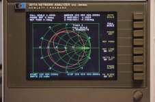
The older Tek curve tracers are strictly analog and the input to the CRT is X-Y stuff. The HP analyzers are computer based and the screen is just a graphic output. The LCD is a huge improvement for the HP instruments. For the Tek you would need appropriate digitizers to drive the screen. Probably a lot more work than it would first seem.
The older Tek curve tracers are strictly analog and the input to the CRT is X-Y stuff. The HP analyzers are computer based and the screen is just a graphic output. The LCD is a huge improvement for the HP instruments. For the Tek you would need appropriate digitizers to drive the screen. Probably a lot more work than it would first seem.
Most of the time that I've had to go in and fix something on the 576 I hold my breath. Only item of issue has been old caps which needed replacement with higher temp electrolytics.
It could be done, not by me. Q678,Q687, Q578,Q587
Attachments
Roll your own
I'm in the process of spinning up my own version of a curve tracer. Nothing special, just tired of rigging up something to match devices, it's really getting old. I don't really care for a scope full of traces, so I went with something different. I'm running a slimmed down version of it now on my wishboard.
I'm in the process of spinning up my own version of a curve tracer. Nothing special, just tired of rigging up something to match devices, it's really getting old. I don't really care for a scope full of traces, so I went with something different. I'm running a slimmed down version of it now on my wishboard.
if you get tired -- in addition to the TEK 576 i've used the u-Tracer:
The uTracer, a miniature Tube Curve Tracer / Tester.
there is a google user group with a lot of great tips, testimonials etc.
The uTracer, a miniature Tube Curve Tracer / Tester.
there is a google user group with a lot of great tips, testimonials etc.
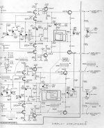
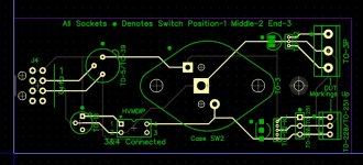
It's fairly easy to mod the Tek 576 to get 15 traces. Pull one IC pin and add a resistor. (pics below) They went to some length to reduce it down to 10.
My old Fuji 8.3 Mega pixel camera works fine for photographing the trace, just need a tripod for steady mounting. Use the zoom to fill the pic.
I modded the stepper amplifier and its V supply to do 14 (x 12V) steps (168V), useful for grid 2 stepping. One can also add an external floating supply for more grid 2 offset. I also changed the 1500V plate V scale to 750V by removing the voltage doubler rectifier scheme.
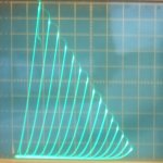
Then I arranged for some variable plate load resistor settings for testing plate current versus grid V (3rd to last pic, a linear ramp for Crazy Twin drive, 2nd to last pic is for normal g1 drive...which sucks!) Last pic is normal g1 drive pentode curves (compare to 2nd pic of Twin/Crazy drive curves).
Also added some switches to control the internal vertical and horizontal select relays, so external X or Y inputs can be used. Very handy for using an AM503 current probe (screen current, grid current)
The X and Y signals going to the display amplifiers could easily be sent to a sound card and stereo digitized. Use Mathcad or something (PC scope software) then to put that file on an X-Y PC graph.
My old Fuji 8.3 Mega pixel camera works fine for photographing the trace, just need a tripod for steady mounting. Use the zoom to fill the pic.
I modded the stepper amplifier and its V supply to do 14 (x 12V) steps (168V), useful for grid 2 stepping. One can also add an external floating supply for more grid 2 offset. I also changed the 1500V plate V scale to 750V by removing the voltage doubler rectifier scheme.
Then I arranged for some variable plate load resistor settings for testing plate current versus grid V (3rd to last pic, a linear ramp for Crazy Twin drive, 2nd to last pic is for normal g1 drive...which sucks!) Last pic is normal g1 drive pentode curves (compare to 2nd pic of Twin/Crazy drive curves).
Also added some switches to control the internal vertical and horizontal select relays, so external X or Y inputs can be used. Very handy for using an AM503 current probe (screen current, grid current)
The X and Y signals going to the display amplifiers could easily be sent to a sound card and stereo digitized. Use Mathcad or something (PC scope software) then to put that file on an X-Y PC graph.
Attachments
-
 rsz_40kg6_triode_7p5vst_50_50.jpg74.6 KB · Views: 261
 -
 rsz_40kg6_twin_3p5vst_888rg2g1_2770rg1k_50_50.jpg74.9 KB · Views: 301
 -
 rsz_1625_807_20ma_50v_12vstepsg2_20kg2g1.jpg79.9 KB · Views: 297
 -
 rsz_26lx6_twin_54v_54vs_50_50.jpg79.1 KB · Views: 262
 -
 rsz_26lx6_26vhtr_g1pentode.jpg82.6 KB · Views: 257
 -
 rsz_26lx6_p.jpg51.4 KB · Views: 83
Last edited:
The X and Y signals going to the display amplifiers could easily be sent to a sound card and stereo digitized. Use Mathcad or something (PC scope software) then to put that file on an X-Y PC graph.
Also pick up the timing pulses from the step generator -- 10ms per pulse.
Easily done with an Arduino and a wifi dongle to your PC or laptop!
I used to own a TEK 576 with high current module. The best thing about it was that TEK made a series of publications on all the ways to use it for a bewildering number of tests.
But I have since replaced it with a new made in china curve tracer which allows me to display 2 transistors' characteristics at the same time on the screen. Wonderful for comparing and matching devices.
THx-RNMarsh
But I have since replaced it with a new made in china curve tracer which allows me to display 2 transistors' characteristics at the same time on the screen. Wonderful for comparing and matching devices.
THx-RNMarsh
I got really lucky with my Tek 576, but I do speak to it in a kindly manner every time I walk past it!
A fellow in California has adapted an LCD screen for various HP analyzers. I haven't gotten around to installing one in my HP 3577A yet, but it's on the list for the fall. Would be wonderful for the Tektronix analyzers, better still if we could export the graphic and data.
I see people have apparently had the same idea with other CRT outfitted gears, some years ago I popped up the hood on an older LeCroy scope of mine and noticed it had an ordinary analog VGA connector and my first thought was to throw out the CRT and adapt it with an LCD, don't know if anyone have done something like that on a LeCroy though.
I see people have apparently had the same idea with other CRT outfitted gears, some years ago I popped up the hood on an older LeCroy scope of mine and noticed it had an ordinary analog VGA connector and my first thought was to throw out the CRT and adapt it with an LCD, don't know if anyone have done something like that on a LeCroy though.
A parenthetical -- the folks at Linear Tech (now part of ADI) seem to be quite fond of LeCroy scopes.
- Status
- Not open for further replies.
- Home
- Design & Build
- Equipment & Tools
- Curve Tracer