Hello all,
I'm an electrician here in Australia.
I can tell you that here, it's illegal to swap the polarity of active ("hot") and neutral. That's because most appliances and devices only switch the active conductor. This goes for sockets and appliances. That's why the wall testers test for this.
If it were to be reversed, a fault could develop and liven a chassis with the device 'switched off'.
I haven't read through the whole thread, but I thought it was worth a mention.
In the UK it is considered good practice for appliances to use double-pole switching (but only one fuse). The big exception is lighting.
Swapping hot/live/line and neutral outside an appliance is dangerous. Swapping the connections to the mains transformer primary inside an appliance should do no harm but in many cases will do no good either. If the device does not have mains isolation then swapping is dangerous. Be aware that many small SMPS (and some larger) will have inadequate voltage isolation so may be more dangerous on one 'polarity' than the other.
What may have caused some confusion is that the word 'polarity' could mean two different things in this context:
1. the AC phase - so reversing polarity means swapping to antiphase AC which has a positive peak where the previous supply had a negative peak etc.
2. which wire is which - so reversing polarity means swapping hot/live/line and neutral conductors at some point
In a balanced mains supply these two are equivalent, but for the usual supply with one side approximately grounded they mean different things.
Then why do you keep posting nonsense and making it our problem?That's not my problem.
we are not going anywhere while you still use the word positive improperly.The problem is when the positive and neutral
being alternating current (properly alternating voltage) being applied alternatively to ends of a floating winding, then anyway you connect them is "the proper/supposed/intended way"are not ending up where they supposed to be designated for
and what´s the problem?and become reversed inside the component.
Being alternating voltage it gets reversed inside the component and anywhere else, back to the generator thousand miles away, 100/120 times a second.
So what?
It is not "a problem", it´s the way it works.
Well, that´s a LIE, pure and simple.For some reason, measurable voltage on the chassis goes up when the correct orientation has not been established.

Now you invented your own version of Physics.
As long as you hid behind "taste" and "subjective opinion" you could somehow claim "I don´t care what you think, that´s how I feel it is", but you just made a Physically impossible statement.
We neither, taste and opinion are personal, won´t waste time arguing that.If it made no difference in sound quality? I would not be concerned.
Confirmation bias / Placebo effect.If I reverse the orientation of one AC adapter powering one component in my system ***I*** can hear a difference in sound.
You can NOT do that on a double blind test.
Won´t comment on the ducks 😛
I noticed that in your latest posts you are getting out of ammunition to answer, so instead of explaining how and why you *think* something is happening, you send us back to reread some old post.
Don´t underestimate us, we have read *all* posts, still find yours unconvincing.
A lot of knowledgeable, respected and above all, patient Forum members have been answering you time and again out of courtesy, trying to help you see how things work in the real worls, or trying to find any phenomenon, however slight and usually irrelevant, which might explain what you claim to hear.
But one by one all rocks have been turned, and there is nothing to be found.
Of course, you will keep claiming : "ah, but I do hear things that way" until the cows come home.
So what?
It proves nothing but your stubborness.
A mains transformer primary is not balanced. One side is likely to have higher capacitance to the core, and hence to the chassis. Hence swapping line and neutral could change the capacitive AC current sent in to the chassis. This should be a small effect, and be of little consequence for most equipment. It is harder to believe that a significant effect occurs with a 12V AC wallwart, as the OP seems to ask in post 1.
It is more important that you understand what you are doing.
From post#109 "Do not flip the polarity". Isn't this exactly what you are doing? You are reversing the way the AC was designed to be connected to a unit. Also, in most of Europe, we use a phase and neutral just like in the US.
Its the common terminology used in America. Electricians check for socket polarity to make sure its been wired correctly. Its just a term we use over here. I realized too late that it would cause confusion over where you live. I had no way of knowing until after I got jumped on... 😉
I tried the Phase-neutral switch and I couldn't hear a difference. I am able to unplug and plug the mains without the amp switching off. It all sounded the same to me. Even with the player on pause and the volume at 10, there wasn't any hum. My problem could be that I didn't expect it to sound any different.
Its not a hum problem. Its a image perspective issue. If all your system is wired for the best "AC orientation" (please forgive me using that term) the ability to reproduce a cohesive image is better realized. Its just one aspect in the quest to hear more realistic sound coming from ones speakers. There are many other aspects involved in realistic sound. The AC orientation is only one of them. If your tweeters are wired out of phase with the mid-woofer? As certain common crossover configurations can cause? The I am not sure how much benefit one will hear. I listen now with full range speakers, and have listened with speakers utilizing first order crossovers. When you have that kind of cohesion potential, then all these tweaks begin to really add up to a more enjoyable - realistic - sound.
Hello all,
I'm an electrician here in Australia.
I can tell you that here, it's illegal to swap the polarity of active ("hot") and neutral. That's because most appliances and devices only switch the active conductor. This goes for sockets and appliances. That's why the wall testers test for this.
If it were to be reversed, a fault could develop and liven a chassis with the device 'switched off'.
I haven't read through the whole thread, but I thought it was worth a mention.
You might just have become a "stirrer" here.
Thank you. I always liked you Aussies. 😉
A mains transformer primary is not balanced. One side is likely to have higher capacitance to the core, and hence to the chassis. Hence swapping line and neutral could change the capacitive AC current sent in to the chassis. This should be a small effect, and be of little consequence for most equipment. It is harder to believe that a significant effect occurs with a 12V AC wallwart, as the OP seems to ask in post 1.
I can not speak for England's system. But, in the US. If a wall wart is not situated correctly ... the same reading problems can be noted with using a VOM meter test.
European wiring may require a different way to test. Google - "Van Den Hul Polarity checker." (Van Den Hul is from the Netherlands and uses the word"polarity." )
Here. Maybe this will help better understand.
I will quote an online source...https://puristaudio.wordpress.com/2009/06/17/correct-ac-polarity/
CORRECT AC POLARITY
June 17, 2009 — puristaudio
System set-up
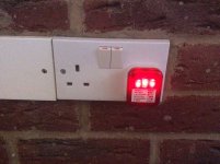
I wanted to talk about a tweak that costs little or nothing to do, while having the potential of paying big dividends in terms of sonic improvement. It involves a simple test (with some simple test equipment) that will allow you to determine if your equipment, and wall outlets, are “polarity correct”. Almost all of your audio equipment has a transformer in it that serves as a source of power for the circuits inside. Not all manufacturers hook up their transformers so as to minimize voltage leakage to the chassis, otherwise called the “chassis to ground potential”. One can measure this by purchasing some testing equipment. What you will be measuring is the amount of voltage running around in the chassis of your audio equipment. The preferred voltage is the lowest voltage, which will save you from making dreadful subjective decisions such as “which polarity is more tuneful and in touch with the musicality?” First thing you will need is a polarity testing plug which will set you back about $3.99. The second piece of test gear is a multimeter (VOM) which reads AC volts below 500; mine cost all of $45.00. The polarity testing plug can be purchased in almost any store that carries even the most meager line of home electronics. It’s a 3-prong plug with three little lights on the back. You take the plug and insert it into each of your wall outlets, and the lights on the back will tell you if your outlets are wired properly in the wall. Many outlets, even in new digs and mobile homes, have the positive and neutral taps wired in reverse and grounds are oftentimes left open. The polarity plug will let you properly assess the orientation of the outlets that you use and make any necessary adjustments. This is the first step toward proper polarity. The next thing to do is check the chassis voltage of your equipment. With your multimeter in hand proceed as directed. Each component to be tested must be totally isolated. Disconnect interconnects, antennas, power cords and grounds. If the component to be tested has a two prong directional cord, plug it in. If the component to be tested has a three prong cord, steal a “cheater plug” from wife’s mixer and use it to float (lift) the ground of the chosen piece of equipment. Set your multimeter to AC volts, connecting the probe to a true ground (I use a true earth ground consisting of an outdoor earth rod with a cable running from it into my listening room). You can also go to the ground connection of the outlet if you have three prong outlets, or you can run to a drain pipe as I had to in my bedroom. NEVER connect to a pipe carrying electrical wiring or anything flammable like natural gas, and NEVER connect to an antenna which can be struck by lightning. Connect the red probe to the chassis ground terminal if it is a preamp you are testing, or to a sheet metal screw on the chassis on almost everything else. With the screws you may have to scrape a little paint off the screw to make good contact. Good contact is essential to an accurate volt reading off the chassis. Now plug the component in and turn it on. If you haven’t been electrocuted, you should have a voltage reading on your meter. Write it down. Turn the component off and reverse the AC power cord in the wall outlet. With a cheater plug, the neutral side of the plug is usually wider than the hot side and reversing can be difficult. In the past I have taken a pair of metal snips and cut the neutral side down so that it will fit into the hot side of the outlet. Once the polarity is reversed, turn the component back on and make a second reading. Choose the power orientation that reads the lowest. (Note: Some equipment, especially power amplifiers, should be left off a few minutes before firing them back up with the AC polarity reversed.) Easy? And with some experience you’ll get to the point where you will be able to tell the proper AC orientation by simply listening to the equipment; the meter won’t be necessary. At that point you will have earned your golden ear. Some audiophiles, when reversing a power cord, choose to leave the ground open or floating, alleging that the system sounds better that way. In some cases it is true, but remember, by floating the ground you may be defeating the UL rating for the device and maybe even voiding the warranty, which could be disastrous if for some reason a fire results. Play it safe. YOU ARE DONE. The real trick here is to get each and every component in a system oriented properly. If your system has two components oriented wrong, the correction of one may not be enough to bring on earth shaking improvements – get the entire system right before passing judgment. Proper orientation makes one’s system generally sound fuller in the midrange and more dimensional in the lower midrange. Clarity and depth of image will increase in good ways. Look for less strident and cleaner highs also a lowering of the noise floor. If on the other hand you test everything and find all the plugs properly oriented already, you could consider the entire ordeal as time wasted, or, you might consider it an average day for an audio manufacturer. Just a note if your not comfortable dealing with AC then don’t try the above post.
https://puristaudio.wordpress.com/2009/06/17/correct-ac-polarity/
Last edited:
Hi Gene, with all audio components connected to mains in proper polarity as explained by DF96 you hear less of the electrical switching of your or your-neighbour's washing-machine, electrical switching, which traverses mains and may get into your stereo.
Hi Gene, with all audio components connected to mains in proper polarity as explained by DF96 you hear less of the electrical switching of your or your-neighbour's washing-machine, electrical switching, which traverses mains and may get into your stereo.
Correct "polarity" through out the entire audio chain .... improves what you end up hearing for other reasons. Finding the correct polarity is like focusing a lens on a camera. The more each component conforms correctly, the clearer the picture will become
I use these here in the states and that noise problem has long been eliminated. I do not know if there is a European counterpart available.
Audio Prism Quiet lines
Last edited:
Difficult to believe that such a change can modify "image pespective".GeneZ said:Its not a hum problem. Its a image perspective issue.
There is a world of difference between mains 'polarity' and tweeter relative phase. The latter will certainly affect the stereo image.If your tweeters are wired out of phase with the mid-woofer?
Nothing new there. However, someone who needs that level of detail should not be fiddling with mains wiring.Here. Maybe this will help better understand.
I will quote an online source...
I have been lurking on this thread with fascination and I'll say right now I'm no engineer but would like to think I have hold of a few of the basics.
After reading the quoted in GeneZ post 127 I thought I'd give it a go.
First off the tests suggested could be potentially dangerous and the jokey attitude could result in serious harm should there be an equipment failure or mains wiring issue. In Europe we are dealing with double the voltage. BE WARNED! A do not touch any of the equipment under test while powered up.
Any new UK property would not get a certificate if the sockets were wired wrong mine is 17 years old and the test says the outlet is wired correctly.
Reading various articles I don't see any fundamental difference in the delivery of uk vs us power other than 240Vac vs 120Vac, 50 vs 60Hz, single/3 phase vs single/2 phase. At the outlet all uk sockets are 3 pin.
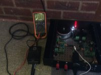
The equipment under test is a home made Modulus86 amp with a conventional toroidal transformer and an emi filter with x y caps to protective ground.
I have a bench top mains breakout box to enable the leads to be swapped.
I find that the test instructions suggest using any earth available. I,d say you have to use the one at the socket. Fire is a risk but the larger is electrocution.
Instead of measuring the ac voltage between the amp chassis and outlet protective ground I measured ac current flow in the line. With the live an neutral correctly wired the leakage current was 253.8uA with L&N swapped it was 271.2uA. A minimal difference but a difference none the less.
Draw your own conclusions my brass ears could not tell any difference.
After reading the quoted in GeneZ post 127 I thought I'd give it a go.
First off the tests suggested could be potentially dangerous and the jokey attitude could result in serious harm should there be an equipment failure or mains wiring issue. In Europe we are dealing with double the voltage. BE WARNED! A do not touch any of the equipment under test while powered up.
Any new UK property would not get a certificate if the sockets were wired wrong mine is 17 years old and the test says the outlet is wired correctly.
Reading various articles I don't see any fundamental difference in the delivery of uk vs us power other than 240Vac vs 120Vac, 50 vs 60Hz, single/3 phase vs single/2 phase. At the outlet all uk sockets are 3 pin.
The equipment under test is a home made Modulus86 amp with a conventional toroidal transformer and an emi filter with x y caps to protective ground.
I have a bench top mains breakout box to enable the leads to be swapped.
I find that the test instructions suggest using any earth available. I,d say you have to use the one at the socket. Fire is a risk but the larger is electrocution.
Instead of measuring the ac voltage between the amp chassis and outlet protective ground I measured ac current flow in the line. With the live an neutral correctly wired the leakage current was 253.8uA with L&N swapped it was 271.2uA. A minimal difference but a difference none the less.
Draw your own conclusions my brass ears could not tell any difference.
Attachments

I just did a simple test. (Passed in posting with the prior one.) I grabbed a 7.5 Volt DC .5A wall wart made in China model YHAD-41-070500U source unknown, but probably from Mouser. Using a Fluke Model 87 True RMS meter on the AC millivolt scale measuring from the outside of the barrel connector to the AC safety ground connection.
With the wall wart plugged in it measured 26 millivolts, turning it around in the AC outlet the measurement dropped to 15 millivolts. Nice steady readings after a few seconds settling time.
No magic, no mystery, pretty basic if you understand what is really going on.
DF I expect the higher harmonic to pass better through a capacitor coupled noise source, so I do not expect hum, rather due to the Fletcher-Munson bit the issue to be reduced signal to noise in the mid-range.
I also measured the current at 300 nanoamps. So that would be -150 dB re the 2 volts CD "0" level with a 200 milliohm shield resistance.
The previous post would only have 109 dB S/N!
Last edited:
Agree.A mains transformer primary is not balanced. One side is likely to have higher capacitance to the core, and hence to the chassis. Hence swapping line and neutral could change the capacitive AC current sent in to the chassis. This should be a small effect, and be of little consequence for most equipment. It is harder to believe that a significant effect occurs with a 12V AC wallwart, as the OP seems to ask in post 1.
It is even harder to believe that sound changes, even less that it "improves"
One step further, it´s even less credible that "system becomes more transparent" or whatever, which is what´s being claimed here and which is such a vague undefined term so as to make us think about subjectivity and confirmation bias or self delusion.
Difficult to believe that such a change can modify "image pespective".
Let it be then... I can't change how things are.
There is a world of difference between mains 'polarity' and tweeter relative phase. The latter will certainly affect the stereo image.
That was just an example of how when things are not all going in the right direction simultaneously they will effect the image and sound.
Nothing new there. However, someone who needs that level of detail should not be fiddling with mains wiring.
No one is fiddling with mains wiring as far as I know. We are just finding out if the component is wired is in sync with the wall's correct format.
I had one (expensive German design) component where I went inside (while it was safely unplugged) and simply reversed the wires for the incoming voltage. Shut the case. Plugged back in. And found when tested, that it was now in agreement with what was coming from the power outlet. The neutral was where it should be, and the hot was as well. Sounded better too. More body when its wired correctly. Sounds thinner when its not.
I have been lurking on this thread with fascination and I'll say right now I'm no engineer but would like to think I have hold of a few of the basics.
After reading the quoted in GeneZ post 127 I thought I'd give it a go.
That only applies to America! Not the UK.
To quote an audio technician I know...
"Here in North America our AC power is single ended 120vac 60hz. This means we get 2 live phases from the electric company, each live phase is 120vac running at 60 cycles. Then they are broken out at the circuit breaker/fuse box, usually 1 live phase runs half of the house and the other runs the other half as they are only rated at so much current. The neutral is connected essentially back to ground, making the electric single ended connection. So yes, in theory we have polarity here in North American because our power is 120v-0v. For 240vac appliances, you have to run both lives to the component and a ground.
Here in North America it is best to make sure it is wired right because I have seen issues with equipment not working with flip flopped wiring (the live is on the neutral feed and cannot start up switching power supplies or such), or also I have seen equipment not work with true balanced power as well that was designed for single ended power. This is usually on equipment with switching power supplies as they are designed completely differently than a conventional linear power supply (which takes the voltages direct to a primary transformer) and they have microprocessors and control chips that need high voltage power before the rest of the circuitry or wont work."
Here in North America it is best to make sure it is wired right because I have seen issues with equipment not working with flip flopped wiring (the live is on the neutral feed and cannot start up switching power supplies or such), or also I have seen equipment not work with true balanced power as well that was designed for single ended power. This is usually on equipment with switching power supplies as they are designed completely differently than a conventional linear power supply (which takes the voltages direct to a primary transformer) and they have microprocessors and control chips that need high voltage power before the rest of the circuitry or wont work."
Last edited:
Instead of measuring the ac voltage between the amp chassis and outlet protective ground I measured ac current flow in the line. With the live an neutral correctly wired the leakage current was 253.8uA with L&N swapped it was 271.2uA. A minimal difference but a difference none the less.
Draw your own conclusions my brass ears could not tell any difference.
How many components do you have in your system? All must be correct to hear the full benefits. Correcting one component only will make no difference if others are still having the same problem. But its not an end all in itself. Its just something one should get right before moving on to other tweaks. Getting things right is not a one shot deal.
Last edited:
GenZ, have you tried this yet?
An externally hosted image should be here but it was not working when we last tested it.
From what I understand? Having a copper ground plane in itself can make audio sound better when in a right application.
Throwing minerals around copper bars connected to a ground? well... There is a market out there for people who have more money than they know what to do with.
I have very little knowledge of these things, and even I know enough to not be bothered. Tweaks that are free and can be done for yourself hold much higher appeal to me.
I would much rather invest my money in a power conditioner of high quality. Preferably, one having a generous sized copper ground bar.
Last edited:
The problem is that these sites and magazines promote products that don't work as advertised. It could be a box filled with sand or wooden blocks for your exotic speaker cables. For me, they are an unreliable source of information. Clearly not something that should be used for designing electronic equipment.
> I don't see any fundamental difference in the delivery of uk vs us power other than 240Vac vs 120Vac, 50 vs 60Hz, single/3 phase vs single/2 phase.
+1
And the 1/2/3 phase is not relevant in domestic audio. "Lighting Circuits" only give you one of however many circuits are used in distribution. And in nearly the whole world, one of those wires is near-ground.
+1
And the 1/2/3 phase is not relevant in domestic audio. "Lighting Circuits" only give you one of however many circuits are used in distribution. And in nearly the whole world, one of those wires is near-ground.
- Status
- Not open for further replies.
- Home
- Amplifiers
- Power Supplies
- Polarity - external 12V AC power supply