Gene give it up now man you've made your point..... several times..... your 'discovery' is
nothing new, magazines etc were advising it years ago .
If you hear a perceived difference in your system then so be it just remember you are talking to many here that have a much deeper understanding of the ' science ' behind electronics than you or I .
Quoting magazines and audio ' experts ' doesn't prove anything , most either have a vested interest in promoting such things or are simply repeating audio ' folklore '.
As for needing a system transparent enough to show any change or improvement i'm never going to agree with that , if something genuinely improves a product then that improvement should , to some extent , be apparent at all levels .
I've ' improved ' non audiophile friends systems that cost a few hundred dollars just by setting it up properly , improvements their ' cloth ears ' can easily perceive no snake oil or the need to learn how to listen involved.
Anyway time to move on don't you think? ... lets talk about speaker cables ? much more fun.......................
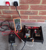
A typical UK circuit socket is part of a ring back to a fuse board. More modern houses are switching to radials. The circuit is protected by a MCB (magnetic circuit breaker) against overload and then the all the rings/radials are protected by a RCBO (Residual current breaker and overload device). This monitors the current going out vs the current returning and will cut out if it is not balanced, typically within 30mA. This protects against failure or harm from electrocution.
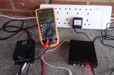
My Audio chain is short, deliberately so, typically it is just my media player, amp & speakers.
The source is a RPi media player that has two internal SMPS's (DAC & RPi) and a EMI filter on the mains side. Measuring that gave me an earth leakage when wired correct (LN) of 444uAac and phase reversed (NL) 444uAac. So no surprise there given the different PSU topology.
Next I thought I'd look at something that uses an AC wall wart that does not use a safety ground. My Rega phono preamp. I also took the opportunity to measure the output of the PSU when disconnected from its load, the preamp.
LN 0.7uAac floating output of 29.60Vac, NL 0.5uAac floating output 29.58Vac.
So in this case, according to the blurb I should swap LN around to make the most of the 2uA & 2V difference. Being a moulded wall wart the only way that can be arranged is to have a separate plug / socket assy. This would not pass UK specs and I would suggest that the added resistance caused by those 2 extra connections may well undo any benefits.
In the test described I'm not sure of the value of voltage testing in respect to the fact that in reality this connection should NEVER be disconnected. It is there for your safety! That is why I measure the leakage current.
Attachments
It was a very poor example, the sort of example seen in snake oil marketing: grab something (anything) which happens to use a similar word or concept in a meaningful significant way and assume that by some magic it applies to the topic under discussion. Aimed at newbies and journalists and rich but ignorant punters.GeneZ said:That was just an example of how when things are not all going in the right direction simultaneously they will effect the image and sound.
Any genuine effect found in America would be approximately twice as strong in the UK.That only applies to America! Not the UK.
Mains polarity as a form of tone control? I don't think so.More body when its wired correctly. Sounds thinner when its not.
Gene give it up now man you've made your point..... several times..... your 'discovery' is
nothing new, magazines etc were advising it years ago .
I did not come here to tell you about something I discovered.
I figured everyone here already knew about it.
That's why I asked my original question. Turns out, I had to end up explaining something that I thought was commonly understood by those working with electronics.
Yeah it started getting confusing for me when it changed from reversing the polarity by swopping the barrel tips at the end with reversed poles on the psu to changing the actual orientation at the wall but i admit i 'm a novice at understanding electric beyond get it wrong and it bites.
The effect is known, although perhaps not as well known as you expected. This may be because in almost all cases it is insignificant. Most people generally spend their time looking at significant issues in audio, not insignificant ones. Then there was some confusion as to exactly what you were asking about, because you made it appear that it was something which important. By this time I expect you were as puzzled as us, but for opposite reasons.GeneZ said:Turns out, I had to end up explaining something that I thought was commonly understood by those working with electronics.
^ That sums it all up nicely, I learned a bit about the hows, whys and wherefores for which I'm grateful 🙂
The effect is known, although perhaps not as well known as you expected. This may be because in almost all cases it is insignificant. Most people generally spend their time looking at significant issues in audio, not insignificant ones. Then there was some confusion as to exactly what you were asking about, because you made it appear that it was something which important. By this time I expect you were as puzzled as us, but for opposite reasons.
I am not confused. It can be important. You would not be confused too if you could hear how what I spoke of effects systems that are capable to revealing what it does.
DF,
Not so sure about the effect doubling in the UK.
Yes higher voltage, but then more turns in the winding, so not sure if that will produce less coupling. The 50 Hz will of course be a bit less.
The bigger issue would be the gain of the audio power amplifier. With a nominal 100 watts into an 8 ohm load the amplifier would require approximately 30 volts RMS. As the CD standard is 2 VRMS any amplifier voltage gain above about 15 would require attenuation of the signal. However the shield noise induced by leakage current would stay the same. So in effect the higher the audio power amplifier gain the worse the signal to noise.
It used to be voltage gain was fairly often 20. But as louder amplifiers "sound" better gain has crept up. I have seen gains of 60.
So perceptually degraded audio quality may be a bit more common, particularly with system level components from different manufacturers with different design ideas.
So in some cases such as gear in the US that has 2 prong unpolarized plugs, easy to test, easy to change.
A not so similar related problem can pop up on larger systems. The amplifiers often are controlled by a low power circuit that often can place the audio power amplifier in a stand-by mode. I have seen the power for this circuitry powered by a single diode rectifier. With enough amplifiers power supplies wired the same there can be clipping of one side of the AC power waveform resulting in power transformer buzz.
Next we could get into why real AC power plants cannot produce perfect sine waves. (It has to do with leaving gaps in the magnetic components to get the winding wire in place!)
So of course in a well designed piece of gear these and other AC supply issues are condidered and avoided or corrected. BUT first one needs to be aware there can be such issues. Please note the folks who contributed here that did not look at the possible issues in enough detail.
Again I wish to remind all not to test for AC mains leakage with their tongue!
This effect will be mainly capacitive, so I would expect double the voltage to produce double the effect. However, 50Hz vs 60Hz will reduce it a little and primaries in series vs primaries in parallel may have an effect depending on exactly how the primaries are arranged. As you said in an earlier post, there is also mains noise/interference at higher frequencies.
Then it depends on how the amplifier/system grounding works - by which I mean how well the designer has derived signal voltages from consistent references rather than random 'ground' points. The widespread confusion on this forum about this issue may be reflected (but hopefully only weakly) in commercial items.
Anyway, we seem to have the usual 'audiophile' issue: a real effect (so difficult to dismiss it) yet so small in competent gear that it should be inaudible. Easier to measure than hear, which may not be what 'audiophiles' wish to discover as they usually prefer to claim the opposite.
And I suspect higher voltage transformers will have less capacitive coupling. Also that reducing the preamps volume control also reduces signal to noise.
As only very good systems have the S/N ratio to exceed 16 bits of resolution that would also limit the ability to perceive this issue.
But again a designer's awareness of the potential problem is to me the real issue. Not so hard to avoid and easy to miss.
Next issue... If I have a downward firing subwoofer can I play an asymmetric waveform that pushes down much faster than up to get the unit to levitate? 🙂
Next issue... If I have a downward firing subwoofer can I play an asymmetric waveform that pushes down much faster than up to get the unit to levitate? 🙂
Of course, in exactly the same way as you can run across water if you pick your foot up as soon as it hits the surface
Not really, because full wave will still average to 0 after any reasonable (still quite short) amount of time.Next issue... If I have a downward firing subwoofer can I play an asymmetric waveform that pushes down much faster than up to get the unit to levitate?
To have a net upwards pushing jet of air, which is what you need to levitate the speaker/cabinet you´d need to have a speaker which can respond down to DC.
Not many of those around, with the possible exception of a plasma speaker.
Then with DC (or averaged DC) applied it would become an Ionic rocket ... one of the suggested motors for deep Space exploration.
But no cone/membrane/dome speaker can do that.
Only small problem 🙂 is that by avoiding downward pressure nothing will balance gravity pull, and you´ll fall towards the center of the Earth.Of course, in exactly the same way as you can run across water if you pick your foot up as soon as it hits the surface
After some 0.45 seconds your 4ss will hit water surface and then picking your feet up won´t help you any more 🙁
Option 2: if you run fast enough (satellite orbiting speed) , then you will never touch water surface, because it follows Earth curvature, no matter how much the flatearther thread guys try to deny that, so it will always "curve downwards" and stay out of reach.
> I suspect higher voltage transformers will have less capacitive coupling.
Why?
Thicker insulation, more turns increases spacing.
Often a transformer uses two primaries so it can be used for both 110V and 240V.
I still can't believe that this can give you the amount of audibility that is being claimed. We are not talking about eliminating anything, just very slightly reducing the amount of current by no more than 15%.
Clearly, it is something that we should take into account when designing audio equipment. Things like where to connect the circuit ground to chassis and how much the transformers within a system interact.
You might just have become a "stirrer" here.
Thank you. I always liked you Aussies. 😉
Anyone who lives in a country that was essentially a huge convict colony surely must love to stir the pot from time to time! 🙂
Thank you. After I asked the question I thought that might be the case.
With speaker hook up? Phase correction is tested when you flip the wires on one speaker to find if they are both in phase. Which proves? Reverse the speaker wires of one speaker and one will be playing in the opposite direction to the other. Again... that is not DC running to the speakers. How can AC be directional? Or, what leaves the amplifier terminals something other than AC?
Now that is just a plain stupid comment. If you could hear the pole reversal with only one speaker playing, I would bow down and pray to your name and call you lord of all things, creator of the universe!

In almost all transformers the primary is many layers. The layer closest to the core couples more to it than the outer layers. Even with a remotely mounted transformer there is capacitance from the primary to the secondary. That is why with even a wall wart the is a difference in AC primary feeds to chassis noise.
What capacitance are you referring to, this is 50/60Hz, not 50/60MHz The fact that it is electromagnetic device means that wound round the core will couple with everything else around the core. 😕
Even the one primary loop with its brother loop around the bobbin. There are currents present in the core named after Eddie, and we try avoiding them to be connected so that it does not become another secondary.😱
What you are trying to say is that more current flows out the live than into the neutral. Thus you are implying that swapping the Live/Neutral we would get some free energy, that being supplied buy the neutral and that being supplied by earth. Earth energy is free given by the lord while that on the live and neutral by the power utility.

If you don't understand what he said why not try to understand it instead of just parading ignorance of stray capacitance and its effects?
- Status
- Not open for further replies.
- Home
- Amplifiers
- Power Supplies
- Polarity - external 12V AC power supply