The two alternatives could make a big difference to the stability margins of the amplifier.
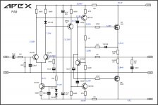
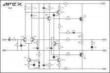
The 220r/180r changes the input LTP current. Increased current increases the open loop gain.
The 680r/2k2 changes the closed loop gain. Decreasing the closed loop gain increases the feedback ratio.
Moving both of these in the same direction could turn a stable amplifier into a oscillator, or a version that cannot reproduce fast signals properly.
I can't understand how these two changes came about without an explanation of their effect.
de
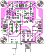
you need to put a footprint on switch base
yes ofcourse, here is the revised one. it seems I did make the previous layout in some hurry. as i put holes threre and not pads!😱
Attachments
Last edited:
Hi Mile,
I found two differences between layout and circuit diagram. What values should I start with?
regards Olaf
Use 180R and 2k2
Regards
yes ofcourse, here is the revised one. it seems I did make the previous layout in some hurry. as i put holes threre and not pads!😱
nice layout.. i think it is much better if you attach the switch base footprint into ground which is just adjacent to it.
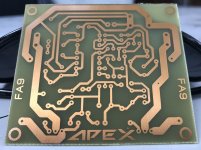
Mile, please check this PSU layout.
Regards
where is the schematic of this psu? i think a version with trimmers to vary output voltage instead of fixed value resistors would be more versatile
FA9
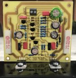
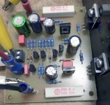
The first board is populated.
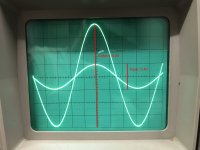
Here are the first measurements:
operating voltage +/- 18V
quiescent current: 17mA (typically Class A 😀)
offset 4mV,
measured voltage gain: 1
no distortion, nice sine, all transistors are (very) cold
regards Olaf
The first board is populated.
Here are the first measurements:
operating voltage +/- 18V
quiescent current: 17mA (typically Class A 😀)
offset 4mV,
measured voltage gain: 1
no distortion, nice sine, all transistors are (very) cold
regards Olaf
Attachments
yes ofcourse, here is the revised one. it seems I did make the previous layout in some hurry. as i put holes threre and not pads!😱
Hi Prasi! Can post the pcb files in pdf format? Thanks!
Someone can answer me what need to change for 2x48V AC? Mr. Mile does not want to answer. Thanks!
An externally hosted image should be here but it was not working when we last tested it.
Sorry, gain is 10
100uF on bias transistor is reverted polarity...
Hi, I have swapped the capacitor. Unfortunately everything is exactly as before. I will check everything again and send more measurements 🙂.100uF on bias transistor is reverted polarity...
regards Olaf
Attachments
Here are the voltages. Input closed to GND.
Resistors are 180R (Emitter BC546 to -V) and 2k2 (basis BC546 to 100u).
Resistors are 180R (Emitter BC546 to -V) and 2k2 (basis BC546 to 100u).
Attachments
Last edited:
Here are the voltages. Input closed to GND.
Resistors are 180R (Emitter BC546 to -V) and 2k2 (basis BC546 to 100u).
Remove 15k resistor... bias must be 1500mA... what is DC offset?
From your measurements look like 820R is 1820R or 15k is 6k8.
Last edited:
15k is removed, 820R is ok. Fets are changed.Remove 15k resistor... bias must be 1500mA... what is DC offset?
From your measurements look like 820R is 1820R or 15k is 6k8.
Offset is 2mV.
Complete circuit takes 18mA (measured in the power lines via a fat 22R).
regards Olaf
15k is removed, 820R is ok. Fets are changed.
Offset is 2mV.
Complete circuit takes 18mA (measured in the power lines via a fat 22R).
regards Olaf
Remove 22R in power lines, replace 2k2 resistor (series with 1N4148 in bias circuit) with 10k trimpot (start with 3k value) measure voltage on 0,68R resistors and set about 1V.
Last edited:
Resistor 2k2 in bias circuit is my mistake and must be replaced with 5k6.
Attachments
Last edited:
work in progress...Resistor 2k2 in bias circuit is my mistake and must be replaced with 6k2.
With 5k6 and without the 15k I can measure 0.8V on 0R68 --> 1.17A
It is OK
- Home
- Amplifiers
- Solid State
- 100W Ultimate Fidelity Amplifier