That's what you think.
I ran in a trouble with it.
It is because front end FETs can't reach operating temperature of their own, without power VFET, because of overcooling.
So can't be set proper operating point for front end.
However, with some patience and practice it can be set correctly, with VFETs on board.
Never mind, I'm a trouble seeker.
Are you using brass standoffs mounted through the eyelets of the pcb to make removable/temporary connections? That's quite ingenious.
Last edited:
Thanks!
I always knew, that all of my genius cannot remain hidden forever! 😉
Yes I have plenty of them, I do use these on regular basis.
I always knew, that all of my genius cannot remain hidden forever! 😉
Yes I have plenty of them, I do use these on regular basis.
I make the second one. 😉
So you can bridge them and get superb mono block's

I'm not in a big rush.
It is good as is.
Although first one (plays Rush now) not exactly finished yet.
So I have a peaceful time (at least I think I have it.) to finish second one first.
Plan is for today to solder all of Dales in place.
It is good as is.
Although first one (plays Rush now) not exactly finished yet.
So I have a peaceful time (at least I think I have it.) to finish second one first.
Plan is for today to solder all of Dales in place.

One of the channels I had a little problem.
On one of the channels I could not set the voltage symmetrically at T6-T7 and T8-T9.
The best what I can set was 0.9V against 2.0V.
Firstly, I suspected it is because that damned input JFETs, so I swapped them between channels.
Sockets are quite good, I think.
Error remained in its place.
So I began to measure impedances, compared good and bad channels.
It revealed quite quickly, one of the 47Ohm resistors for driver FETs were about 90Ohm.
It was a Caddock 915.
I have measured it before, so I was quite surprised.
As you know, I'm overjoyed everything.
Perhaps I have tightened more than enough the screw for poor Caddock.
Maybe it has some crack because of this, and it changed the value.
Never mind, I had another one.
But it costs to me about four bottle of beers. 🙁
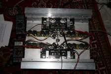
There is something really strange.
As I wrote above, I have changed 47Ohm resistor.
I've set up a test for approx. 1.5A current, as shown in the photo.
It worked like a charm about a hour or so, with cc. 5mV offset.
Then I wanted to set it as it should be.
There was a huge DC offset, and mismatch between test points T6-T7 and T8-T9, just as before!
That resistor, what I've changed, showed about 56Ohm, instead of its original 47Ohm value.
I really didn't hurt it, so I'm now really puzzled.
Only one reserve left.
I really didn't hurt it, so I'm now really puzzled.
I say excessive self-confidence is not always good. 😉
The whole mess above is certainly my fault.
Those two Caddocks went south by me.
(There are as many as eight bottles of beer. 😡 )
Most probably over tightened bolts, or perhaps I wasn't be careful enough when I bent those legs, or when I drilled M3 holes.
Second case was quite frightening, because it worked more than a hour.
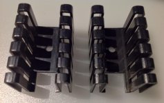
Soundhappy, I don't use those little heatsinks.
All of the parts (2SK2013/2SJ313and Caddock MP915 47Ohm resistors) are thermally coupled with each other and main heatsinks.
It's been stable for over two hours now. 🙂
Last edited:
- Status
- Not open for further replies.
- Home
- Amplifiers
- Pass Labs
- Gyuri's Pass SONY VFET2 build.