When we are into IR land exchange here are a fun view discovered if we like see IR without acoustic grass as being outside probably also lifted above surface : )
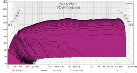
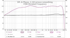
Set REW measurement window to FDW 1/6 width in octaves and after that divide on "All SPL" tab with DC-light speed IR offset in amplitude to zero dB, and to get that either create it in Rephase at same sample rate or divide own measurement with itself will out put a perfect IR.
I'm not really sure what the theory behind this is but it is fun to fiddle with REW and get to know what it can do.
I did that to the single TC9 measurement with no EQ and this is what I got. The waterfall settings will be different but if I set 20 ms I just got a solid block!
Attachments
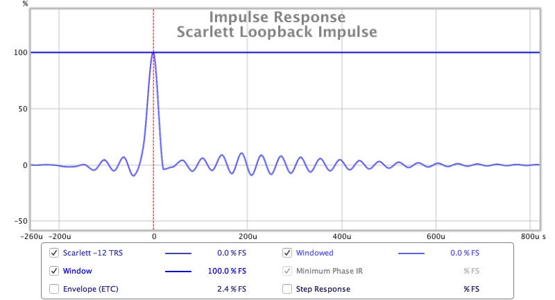
I ran a couple of tests this morning and the Scarlett is definitely the cause of the pre ringing which can be seen in a loopback impulse response. So there is one mystery solved.
However now I have an even bigger one. I tried to measure another DAC feeding the REW output to it and then into the Scarlett input.
This is what I get as a measurement, repeated it three times and closed down REW and re opened changed all the input and output settings and it is exactly the same. Looks like someone put a 2.5K High pass filter on it, I don't know how, there is nothing else in the chain the Mac OS doesn't have any hidden processing. Both are connected by USB with no separate driver as the Mac is USB class compliant so they just work without them. There is no filtering in REW for the IR or smoothing in the graphs. I made a normal measurement of the Scarlett only moments before.
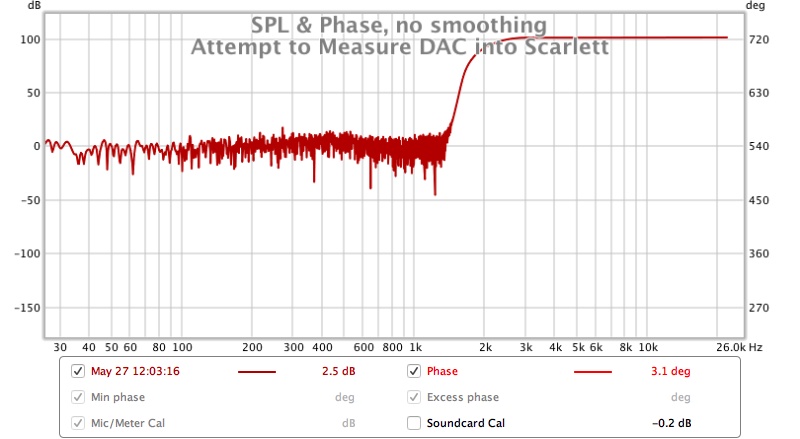
I have listened to Pink Noise, Sine waves and a measurement sweep on the Scarlett using the zero latency input monitoring so I am listening to what is coming in to the device and it sounds normal. If I play a 100Hz tone and check the RTA, there it is as expected not filtered out.
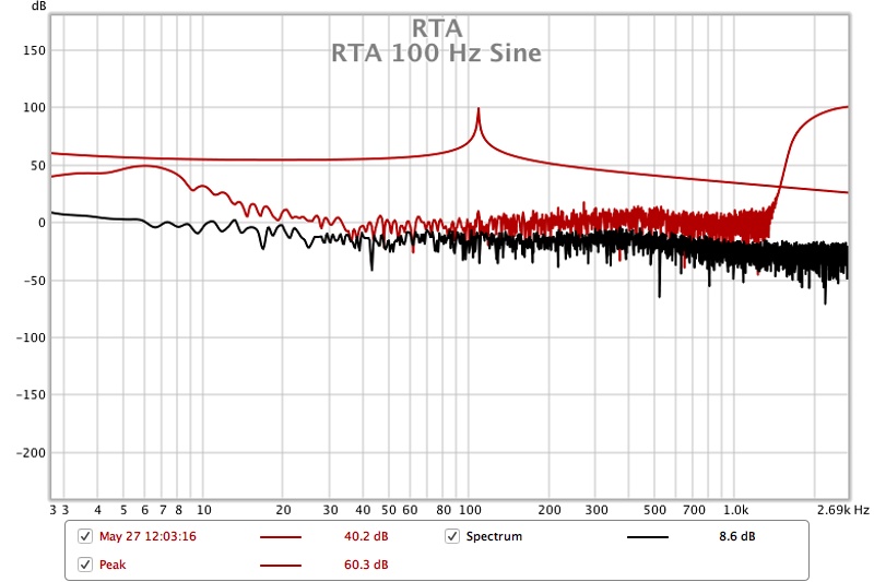
WTF is going on 😱 If anyone has any thoughts let me know
However now I have an even bigger one. I tried to measure another DAC feeding the REW output to it and then into the Scarlett input.
This is what I get as a measurement, repeated it three times and closed down REW and re opened changed all the input and output settings and it is exactly the same. Looks like someone put a 2.5K High pass filter on it, I don't know how, there is nothing else in the chain the Mac OS doesn't have any hidden processing. Both are connected by USB with no separate driver as the Mac is USB class compliant so they just work without them. There is no filtering in REW for the IR or smoothing in the graphs. I made a normal measurement of the Scarlett only moments before.
I have listened to Pink Noise, Sine waves and a measurement sweep on the Scarlett using the zero latency input monitoring so I am listening to what is coming in to the device and it sounds normal. If I play a 100Hz tone and check the RTA, there it is as expected not filtered out.
WTF is going on 😱 If anyone has any thoughts let me know
Attachments


2L rear chamber sims
OPC,
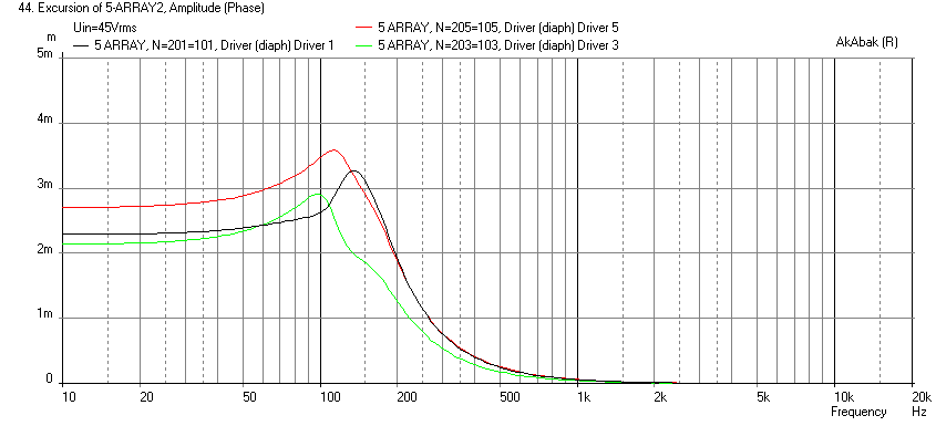
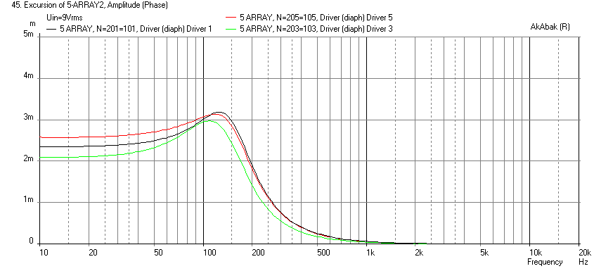
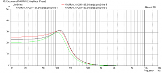
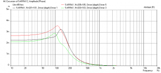
Here are the simulations of the cone displacements for a 2L rear chamber per driver, with 9V (parallel) and 45v (series) with stuffing in rear chamber.
SERIES:
PARALLEL:
OPC,
xrk971,
Could you do me a huge favor and run the simulations again with two small (and presumably simple) changes?:
1. Change rear volume to 2L per driver. This is more representative of what myself and fluid are using.
2. Change input voltage to 9V for the parallel case and 45V for the series case. Running 3V in the parallel case works out to 28W for the entire array, and they require a whole lot more power than that. 9V works out to more like 250W which is what I needed to get down to 20-30Hz at decent output levels in a mid-sized room. It's still quite a bit less than the maximum power capacity of the array.
I think these two changes will help to better demonstrate the issue. All I need to see are the excursion graphs.
Here are the simulations of the cone displacements for a 2L rear chamber per driver, with 9V (parallel) and 45v (series) with stuffing in rear chamber.
SERIES:
PARALLEL:
Attachments
I'm more convinced that it is the DAC filter now but I suppose most measurements will have some amount of power line hum if you look that closely! If I set estimate IR delay it looks less symmetrical.
I have exported the IR and attached in a zip. Mine was much smaller in size so no need to rename.
Maybe you could download it and show me a screenshot of what you mean in the filtered IR? I am by no means an REW expert so we could be going backwards and forwards otherwise.
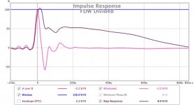
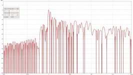
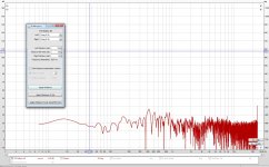
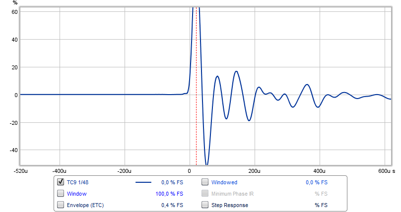
Here's the graph I was looking for:
I wanted to see at what level the disturbance before the peak was. It's at ~-30 dB (as expected by the size of the ripple).
Now if I set the window timing to look at everything that happens before the main impulse:
All we see sticking out above the ground noise is a peak at just under 24 KHz.
Big chance that a DAC filter is the cause.
Attachments
After a day of messing with different DAC's and computers I have been able to get better measurements. I still don't know what was going wrong but I somehow I have got round it. I tried using windows with an optical connection from the motherboard sound to the DAC and then through the Scarlett. That did not work the measurements stopped at 200 Hz instead.
I tried passing spdif through the Scarlett, that just did not work at all. Then I went back to USB to both DAC and Scarlett on Windows using Java Drivers and that was what worked!
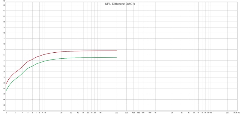
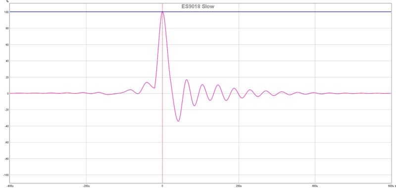
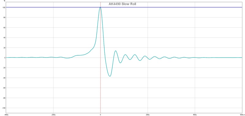
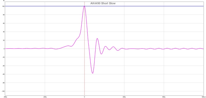
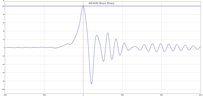
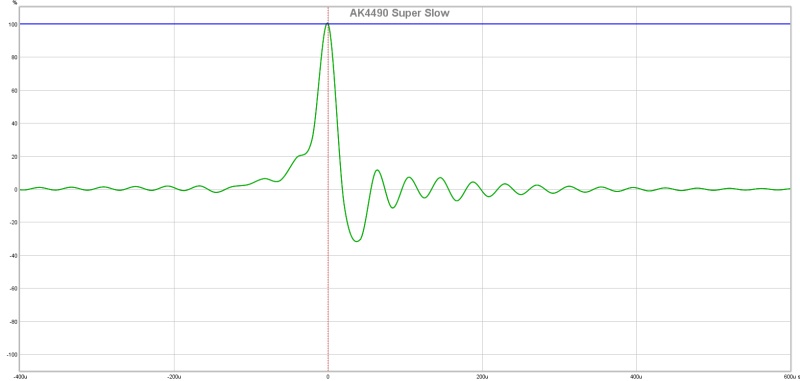
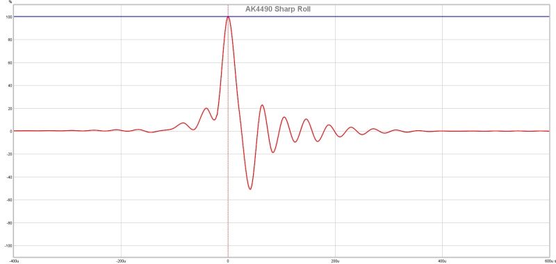
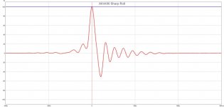
Anyway I have been able to run measurements on two different DIY DAC's one is a dual AK4495 which for some reason I labelled as AK4490 in the graphs. That has 5 different filter settings. The other is the LKS ES9018 kit which just has fast or slow.
I think I might know the reason for the soft slope that came from the Najda and it is not the SRC but the actual filter in the DAC chip as you can choose between fast and slow. I had it set to slow. All of the slow filters seem to have that soft ramp pre ringing in them.
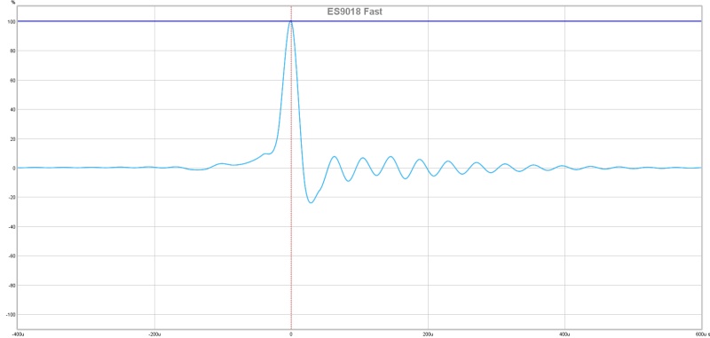
I have listened to all of them and I can hear some slight difference in the AK4495 filters but absolutely no difference with the ES9018 between fast and slow. I don't think a little ringing in the impulse is a issue for the sound but it does make measurements of other ringing very difficult as how do you know what comes from where.
Here are the graphs
I tried passing spdif through the Scarlett, that just did not work at all. Then I went back to USB to both DAC and Scarlett on Windows using Java Drivers and that was what worked!
Anyway I have been able to run measurements on two different DIY DAC's one is a dual AK4495 which for some reason I labelled as AK4490 in the graphs. That has 5 different filter settings. The other is the LKS ES9018 kit which just has fast or slow.
I think I might know the reason for the soft slope that came from the Najda and it is not the SRC but the actual filter in the DAC chip as you can choose between fast and slow. I had it set to slow. All of the slow filters seem to have that soft ramp pre ringing in them.
I have listened to all of them and I can hear some slight difference in the AK4495 filters but absolutely no difference with the ES9018 between fast and slow. I don't think a little ringing in the impulse is a issue for the sound but it does make measurements of other ringing very difficult as how do you know what comes from where.
Here are the graphs
Attachments
-
 Different DACs.jpg65 KB · Views: 473
 -
 AK4490 Sharp Roll.jpg44.9 KB · Views: 928
 -
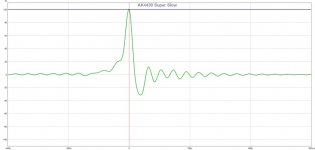 AK4490 Super Slow.jpg44 KB · Views: 473
 -
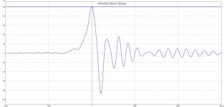 AK4490 Short Sharp.jpg48.3 KB · Views: 490
 -
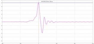 AK4490 Short Slow.jpg43.8 KB · Views: 466
 -
 AK4490 Slow Roll.jpg42.4 KB · Views: 469
 -
 ES9018 Slow.jpg43.2 KB · Views: 493
 -
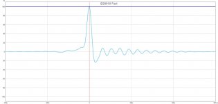 ES9018 Fast.jpg42.1 KB · Views: 481
 -
 DAC Impulse Comparison.jpg92.6 KB · Views: 471
Here's the graph I was looking for:
All we see sticking out above the ground noise is a peak at just under 24 KHz.
Big chance that a DAC filter is the cause.
Thanks for doing that, another reason to blame the reconstruction filter!
Those impulse curves look like a classic textbook case of an underdamped system. I remember seeing such curves using modelling software while taking Electrical Engineering Coursework in college.Here are the graphs
This can apply to both mechanical and electrical signal filters, for instance when designing a "fuzzy logic" control system in which oscillations in an industrial environment may take some time, to an amplifier with negative feedback in the output.
In a system with no damping at all, oscillations can persist for some time or actually cause a runaway condition in active systems. In an underdamped system, a change in the input will cause oscillations in the output which stabilize after a period of time. In a critically damped system, a change in the input will cause a rise or fall in the output that stabilizes after a minimal period of time with no oscillation. This is desirable and systems should strive for critical damping for fastest response time. Finally, in an overdamped system, the output resists change, and a change in the input will create a gradual change in the output which will slowly stabilize but take longer to do so.
In terms of driver design, the spider and surround contribute to damping cone movements and a good driver will be critically damped so that the cone does not resonate at the resonant frequency when a change in input is applied. Overdamping would reduce efficiency and hf response, while underdamping of the cone would cause the cone to resonate when a voltage is applied. You want resonance in a musical instrument like a guitar body or drum set for instance, but this would be extremely undesirable for a driver or it's enclosure.
Last edited:
OPC,
Here are the simulations of the cone displacements for a 2L rear chamber per driver, with 9V (parallel) and 45v (series) with stuffing in rear chamber.
SERIES:
PARALLEL:
Interesting to see the difference. The series seems to have about a 0.6 mm excursion difference between drivers while the parallel case stays within ~0.2mm.
The series connected string has one driver hitting x-max and the shape of excursion seems influenced on the driver with the least excursion.
The top where the excursion is greatest also varies more between both models.
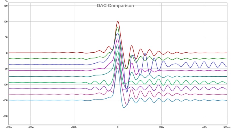
Whilst all true it doesn't have much to do with the anti aliasing filter in a DAC. All filters ring in the time domain which is what is shown in the graphs. A linear phase filter like those used rings on both sides pre and post. The filter designers can trade the ringing to whichever side they think is best which is why they look different. You can see in Byrtt's images before his preferred card has no pre ringing but increased post ringing as a result. That is the downside to the steep band limiting filters needed to avoid aliasing artefacts.Those impulse curves look like a classic textbook case of an underdamped system. I remember seeing such curves using modelling software while taking Electrical Engineering Coursework in college.
This can apply to both mechanical and electrical signal filters, for instance when designing a "fuzzy logic" control system in which oscillations in an industrial environment may take some time, to an amplifier with negative feedback in the output.
In a system with no damping at all, oscillations can persist for some time or actually cause a runaway condition in active systems. In an underdamped system, a change in the input will cause oscillations in the output which stabilize after a period of time. In a critically damped system, a change in the input will cause a rise or fall in the output that stabilizes after a minimal period of time with no oscillation. This is desirable and systems should strive for critical damping for fastest response time. Finally, in an overdamped system, the output resists change, and a change in the input will create a gradual change in the output which will slowly stabilize but take longer to do so.
In terms of driver design, the spider and surround contribute to damping cone movements and a good driver will be critically damped so that the cone does not resonate at the resonant frequency when a change in input is applied. Overdamping would reduce efficiency and hf response, while underdamping of the cone would cause the cone to resonate when a voltage is applied. You want resonance in a musical instrument like a guitar body or drum set for instance, but this would be extremely undesirable for a driver or it's enclosure.
As a test I shorted the input cables together and pushed on the cones, the others didn't move or if they did I couldn't see it. Maybe because it is series parallel wired it nullifies the effect of a pure series connection.
I'm not really sure what the theory behind this is but it is fun to fiddle with REW and get to know what it can do.
I did that to the single TC9 measurement with no EQ and this is what I got. The waterfall settings will be different but if I set 20 ms I just got a solid block!
We can agree its fun to fiddle with REW but maybe not for examples theory and that's alright. In my thinking we get room hash out of picture using FDW and also any excess phase from alias filters and other stuff get averaged out by the divide, so this new picture would probably be good base for minimum phase EQ correction, although some experimenting for window size would probably benefit to get as close to truth for actual system and room, in my environment it could look like base EQ for LF 1/3 window, MF 1/6 window, HF 1/10 window gets good results.
I ran a couple of tests this morning and the Scarlett is definitely the cause of the pre ringing which can be seen in a loopback impulse response. So there is one mystery solved...
...

...WTF is going on 😱 If anyone has any thoughts let me know
Looks like when OS shall handle audio stream from two physical USB ports at same time you get WTF happenings, have you tried change physical port.
I don't ever recall a TC9FD impulse that I measured ringing like that - similar to an aluminum cone driver. One thing you can try to sort this out to see if it is real is to run an RTA. Set the generator to the ring frequency and look at RTA to see if that frequency rises when tune excitation around that point. You should be able to hear it if it is audible range. RTA will show it as well. Or try harmonics excite at 1/2, 1/3, 1/4 of f.
I don't ever recall a TC9FD impulse that I measured ringing like that - similar to an aluminum cone driver. One thing you can try to sort this out to see if it is real is to run an RTA. Set the generator to the ring frequency and look at RTA to see if that frequency rises when tune excitation around that point. You should be able to hear it if it is audible range. RTA will show it as well. Or try harmonics excite at 1/2, 1/3, 1/4 of f.

We first need to determine if the "ringing" is an artifact of the speaker array, the amp, or the DSP, but IMO it does not matter. I am counting roughly 4.5 oscillations over a period of 200 microseconds. That gives a wavelength around 44 microseconds.
1/.000044s = 22,500Hz, so this "resonance" is above the range of human hearing and should be completely inaudible, whether caused by the speakers, amp, or DSP is irrelevant. And my rough estimate by eyeballing the graphs is right at half the sample rate of 44.1kHz CD audio or 22.05kHz, so the 22kHz ringing is very likely a DSP artifact.
Last edited:
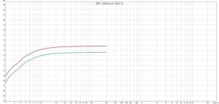
...Oops, forgot the zoom. I exported an imported mine because your's was normalised they look more similar now. I think your cardboard must load the driver better because you have much more low frequency output and a smoother response overall. I think the balance of more high frequencies is what is causing my impulse to swing lower than yours.
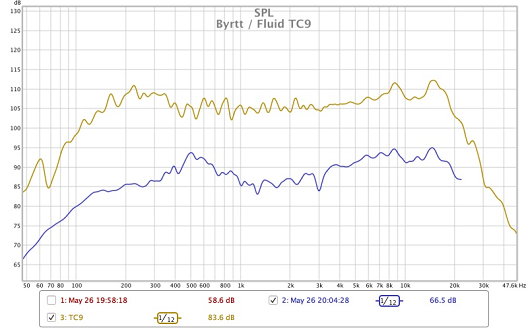
Right spotted my cardboard size is bigger and that point plus different ringing schemes of our ADC/DAC chains think makes your measurements look good now after we got rid of the attack side masking pre-ringing of filters and the decay side that had way to high negative peak.
Attachments
I hope you guys realise we were looking at loop back impulses from 2 different DAC's 🙂.
No driver, no microphone... high frequency stuff at cut off frequency about 30 dB below the normal driver output. Though lesser results than that for the worst case as quoted.
No driver, no microphone... high frequency stuff at cut off frequency about 30 dB below the normal driver output. Though lesser results than that for the worst case as quoted.
Last edited:
Yup, when I measured the period of oscillations in my previous post, it almost perfectly corresponds to half the redbook audio sample rate of 22.05kHz.I hope you guys realise we were looking at loop back impulses from 2 different DAC's 🙂.
No driver, no microphone... high frequency stuff at cut off frequency 30 dB below the normal driver output.
Derp.
...Looks like when OS shall handle audio stream from two physical USB ports at same time you get WTF happenings, have you tried change physical port.
Come to think about other than try change physical USB port, try lower or higher "Length" settings in REW "Make a measurement" window, I'm mostly for lower setting would improve and higher setting make things worse.
I plan to try a few different EQ schemes to see what the difference is. I like the idea of the beamforming measurement technique where the results are spatially averaged rather than frequency windowed. The new REW beta has a few tricks to make that a bit easier which is good news. Given that I won't have any room treatment I doubt a single point measurement will cut it.We can agree its fun to fiddle with REW but maybe not for examples theory and that's alright. In my thinking we get room hash out of picture using FDW and also any excess phase from alias filters and other stuff get averaged out by the divide, so this new picture would probably be good base for minimum phase EQ correction, although some experimenting for window size would probably benefit to get as close to truth for actual system and room, in my environment it could look like base EQ for LF 1/3 window, MF 1/6 window, HF 1/10 window gets good results.
Macbook only has two USB ports so it is hard to swap! I thought it might be that which is why I tried with the optical but that was just as WTF in a different way. Eventually got it to go by using USB ports on the back of the motherboard for both. The XMOS driver for the AK DAC needed to be installed with driver signing bypassed which I had forgot about so there was more head scratching there before I remembered.Looks like when OS shall handle audio stream from two physical USB ports at same time you get WTF happenings, have you tried change physical port.
All the last impulses were pure loopback connections to show the effect of the DAC by itself no TC9's were harmed in the making of those! The effects are still visible in the acoustic measurements but they are covered more by the driver.I don't ever recall a TC9FD impulse that I measured ringing like that - similar to an aluminum cone driver. One thing you can try to sort this out to see if it is real is to run an RTA. Set the generator to the ring frequency and look at RTA to see if that frequency rises when tune excitation around that point. You should be able to hear it if it is audible range. RTA will show it as well. Or try harmonics excite at 1/2, 1/3, 1/4 of f.
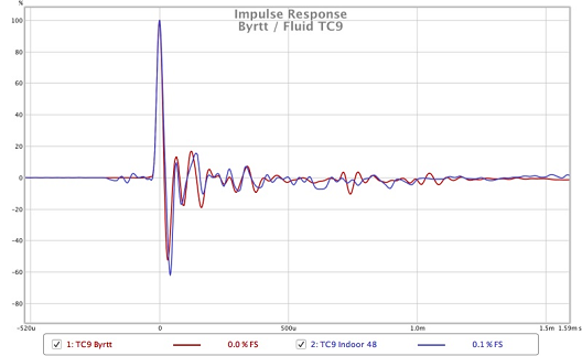
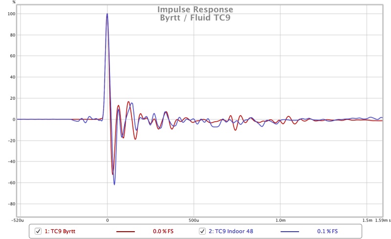
This comparison of Byrtt's and mine is show the shape is very close but the pre ringing can still be seen as well as the greater post ringing from Byrtt's DAC.
There was no DSP and no speaker just a loopback 🙂We first need to determine if the "ringing" is an artifact of the speaker array or the DSP.
This comparison of Byrtt's and mine is show the shape is very close but the pre ringing can still be seen as well as the greater post ringing from Byrtt's DAC.
I hope BYRTT can post a loopback result of his measurement setup used for this cardboard/TC9 measurement. I really doubt you will see a higher level of post ringing in his setup. As for the differences after the main pulse, it could be anything really, but I doubt it's post ringing of the DAC that far out from the main pulse.
I wouldn't be surprised if all of it was calibrated like this.
Last edited:
I hope BYRTT can post a loopback result of his measurement setup used for this cardboard/TC9 measurement. I really doubt you will see a higher level of post ringing in his setup. As for the differences after the main pulse, it could be anything really, but I doubt it's post ringing of the DAC that far out from the main pulse.
There has been so many posts recently that you might have missed it but he already posted a comparison of his Behringer vs the one he is using in the TC9 measurements, and there is more post ringing when I look at it.
Post here
http://www.diyaudio.com/forums/full-range/303417-full-range-tc9-line-array-cnc-cabinet-47.html#post5090456
Image
The main difference in the impulse is the fact that they don't have the same frequency response but the general trend is there which is why they look quite similar.
The post ringing there is still evident to nearly 600u which is the bulk of the IR. Byrtt will have to answer if he calibrated it away in that measurement in the same way as the post you referenced.
Thanks for showing that post as that could be a good way to measure and be sure of where the ringing comes from. The standard calibration is only really frequency response which in most good soundcards is pretty good anyway.
Last edited:
- Home
- Loudspeakers
- Full Range
- Full Range TC9 Line Array CNC Cabinet