Thanks those close pictures of setup fluid and rule out mismatch in sample rate, can we bench one device at a time or take one out at a time to see when things suddenly gets improved 
1. You should be able to run I/O on FocusRite alone and if that improves things it may point on Najda and can think of two points into Najda as could be teasing either SRC or USB interface.
2. Guess its possible on FocusRite turn off Phantom power which is probably very important and then connect Najda single ended out to particular same microphone input on FocusRite where Sonarworks calibrated measurement mic sits right now, think use pseudo figure 6 from Bruno Putzeys pdf document as we talked about over wesayso's thread so as we get hot/cold as mic use right now real tested. Also think start with mic gain fully counter clockwise would be wise here and then open a little bit at a time, run this loop test and see what happens. If this improves things can think of maybe mic mount have a unfortunate form or wearing too much clothes.
Hope you feel okay above work and it will tell us something so time ain't wasted here.
Last edited:
Center material mixed for a true center will sound different on a stereo setup.
Much like that "clarity boost" you talk about. Much more info is available in this thread.
Thanks wesayso. I'll read up on it.
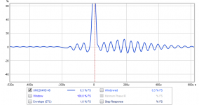
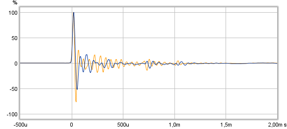
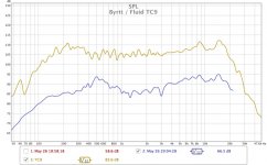
If it can help here comparison between fluids new single TC9 at 48kHz IR on presumable Australian cardboard as upper one and mine 192kHz chain of single TC9 onto European cardboard as lower one, tried again tweak same scales and color.
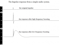
Not only take off at attack side of IR looks non textbook also as wesayso spottet agree bit strange how high downward peaks, if we look at below visual guidance from think it was Wikipedia then there got to be some enormous VHF frq boosting taking place somewhere.
Not only take off at attack side of IR looks non textbook also as wesayso spottet agree bit strange how high downward peaks, if we look at below visual guidance from think it was Wikipedia then there got to be some enormous VHF frq boosting taking place somewhere.
It's strange though, the peak that hits 100% is the downward one....
Attachments

Thanks those close pictures of setup fluid and rule out mismatch in sample rate, can we bench one device at a time or take one out at a time to see when things suddenly gets improved
1. You should be able to run I/O on FocusRite alone and if that improves things it may point on Najda and can think of two points into Najda as could be teasing either SRC or USB interface.
2. Guess its possible on FocusRite turn off Phantom power which is probably very important and then connect Najda single ended out to particular same microphone input on FocusRite where Sonarworks calibrated measurement mic sits right now, think use pseudo figure 6 from Bruno Putzeys pdf document as we talked about over wesayso's thread so as we get hot/cold as mic use right now real tested. Also think start with mic gain fully counter clockwise would be wise here and then open a little bit at a time, run this loop test and see what happens. If this improves things can think of maybe mic mount have a unfortunate form or wearing too much clothes.
Hope you feel okay above work and it will tell us something so time ain't wasted here.
Byrtt it's good we have you around to remind us what's under our noses sometimes

I ran a loopback on the Scarlett to make a cal file at 48K balanced to balanced using the same mic input.
I then ran the measurement again with the input gain turned down a little and the level up, I think that helps to reduce the background noise as I was seeing -60 on the REW meter with the mic open whereas before it was closer to -45.
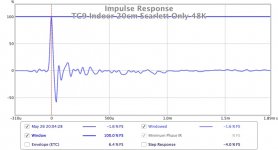
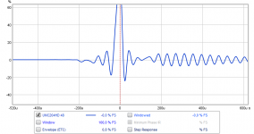
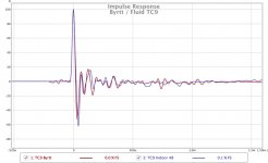
This is the impulse, much better still a little bit of a wiggle before the peak but nothing like before so I think we can say that most of it was coming from the Najda.
I will do a loopback measurement of the Najda through the Scarlett to see what it looks like and also the impulse of the Scarlett by itself but I have run out of time tonight.
The mic mount could be part of it too and I will just strap it straight to the stand to see if there is a difference. I thought I had a standard mic clip but if I do it is hiding. That mount came from a Behringer studio mic that was made to look like a Neumann U87, not for a slim measurement mic!
Attachments
If it can help here comparison between fluids new single TC9 at 48kHz IR on presumable Australian cardboard as upper one and mine 192kHz chain of single TC9 onto European cardboard as lower one, tried again tweak same scales and color.
Not only take off at attack side of IR looks non textbook also as wesayso spottet agree bit strange how high downward peaks, if we look at below visual guidance from think it was Wikipedia then there got to be some enormous VHF frq boosting taking place somewhere.
I posted a new one that looks much more like yours. Still not a straight line until the pulse though hmm. Maybe the Java drivers from REW on the mac could be responsible if not the mic mounting. I will run a test on a windows machine to see if there is any difference. I remember you or wesayso saying that tweaking buffer settings had an effect on the impulse so maybe that might do something which goes completely against logic but software is like that sometimes.
I can't remember where the cardboard came from, but I suspect that both your's and mine could have come from China!
...This is the impulse, much better still a little bit of a wiggle before the peak but nothing like before so I think we can say that most of it was coming from the Najda...
Wow much better a little pre ringing is much more normal at attack side and downward peak at decay side starts look normal too, glad we move forward spending time on this. On Windows using two USB soundcard interfaces at same time can also sometimes be weird even they when run each by each bench a loop perfect, sometimes changing to another physical USB port helps and often think its IRQ sharing related on that platform, but lets see where next test brings you on a fresh new day.
Last edited:
The general shape is good this time. The stuff before the pulse comes from somewhere in the chain but at least it's not altering the shape anymore.
What does it look like on the filtered IR tab? It doesn't look like the pré ringing from buffer settings to me, that's more regular in shape like this:

It looks like some pré noise before the start of the measurement. It should show up before the peak in the filtered IR tab.
It looks like some pré noise before the start of the measurement. It should show up before the peak in the filtered IR tab.
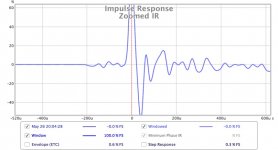
This is the impulse zoomed in to show a clearer view of what happens before the peak. There is a very straight line until -200u when the wiggles start...
Could be wrong but if you ask me and that FocusRite have the fine Xmos USB asynchronous chip combined Cirrus converters as is case for Behringers UMC204HD it looks we get modern looking ringing schemes, look at first below for that interface I/O looped when IR is not aligned with button "Estimate IR Delay" from minus 200uS -100uS it looks exactly as yours but it change look when IR is aligned with "Estimate IR Delay" button as shown in second visual, sample rate was at 48kHz and for this interface I can't stand the weird ringing schemes it perform at various sample rates, only exception is up at 192kHz it start look fine but then can't use it as native player card so its only for measurements or parked on a shelf.
Third one is good old M-Audio AP192 measuring TC9 at 192kHz with new zoomed scales as yours, this card performs great at whatever rate its run and why i use it on player and measurement computer.
EDIT: wrong words used above in 200uS -100uS don't look exactly same but scheme is very close.
Attachments
Last edited:
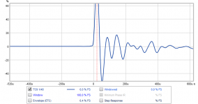
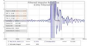
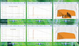
These are some graphs from the filtered IR, is what you mean?What does it look like on the filtered IR tab?
63 is probably power line hum
I will check the pure loopback IR to see what it looks like. It is possible that a linear phase brickwall filter has been used in the DAC section and that is what is causing the pre ringing. It may be that your m-audio uses a minimum phase reconstruction filter which does not have pre ringing. I can check my other DAC's too to see the differences.it looks we get modern looking ringing schemes,
To compare our two single TC9 IR in overlays window hang on exportet IR below and actual think they looks close, file extension was renamed from zip folder to dot asc because size extends limit for zip files, when downloaded rename extension to dot zip.
Like this?
Attachments


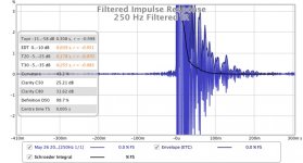
This will work 🙂. I figured to look at it in %dB instead of %FS but you've gone searching for the separate components creating the disturbance.
It does look like that hum is the cause of the most benign pré ringing. I't still rather low as should be seen in the %dB mode (change it within graphic's window upper left).
It might be some power line hum as you indicated or being caused by DAC filters.
If you let REW center the peak does it look more like a growing sine instead of this irregular wave shape? Like in BYRTT's example?
I will check the pure loopback IR to see what it looks like. It is possible that a linear phase brickwall filter has been used in the DAC section and that is what is causing the pre ringing. It may be that your m-audio uses a minimum phase reconstruction filter which does not have pre ringing. I can check my other DAC's too to see the differences...
Probably right about reconstruction filter is mostly using digital filters to save on component numbers and in its lower cost soundcard they also save on better intelligent firmware that shift to best filters based on sample rates but instead use one and same filter for all rates.
...Like this?
Ha ha grass all over there was thinking of more normal IR view as shown earlier on ala in below example between TC9 and SB65.
Attachments
Last edited:
The following is a good experiment to show the effect of back EMF: connect four speakers in series and short the positive and negative input leads of the series circuit. Push down on one cone with your hand; you will notice that the three other speakers will move in the opposite direction of the one you are pushing. Now, reconnect the speakers in parallel, short the inputs and push down on one cone. The speakers will not modulate each other because each one is shorted directly.
Yep. I have done this and seen it many times. It moves rather well in fact. I had one speaker (vented) where I laid it on its back wit both drivers aimed up. I put small washer on the dustcap on one and tapped the other with my finger. It sent the washer flying.
This also shows how effective an old driver with a resistor connected across the terminals can be a good damped passive radiator with adjustable damping.
Fluid,
That is a very nice Focusrite. It is is huge, the mother of all Scarletts! What model is that and how many independent output DACs does it have?
That is a very nice Focusrite. It is is huge, the mother of all Scarletts! What model is that and how many independent output DACs does it have?
Hi guys - regarding the series/parallel issue - thought I would share a bit of information that may or may not be relevant when looking into the wiring of my planned subwoofers:
This was taken from JL Audio's website (apologies if you have already seen this):
It is far less desirable to make subwoofer to subwoofer connections in series. Due to slight and unavoidable differences between speakers and the high likelihood of uneven loading between different speakers in a car, there will be slight differences in the mechanical behavior of the two speakers in series. These differences in movement result in the creation of induced voltage (called back EMF) by the speakers across the series connection. This effect causes a problem when two speakers that behave differently are connected in series because the speakers can modulate each other (cause each other to move), resulting in distortion. The problem becomes more serious as more speakers are connected in series.
The following is a good experiment to show the effect of back EMF: connect four speakers in series and short the positive and negative input leads of the series circuit. Push down on one cone with your hand; you will notice that the three other speakers will move in the opposite direction of the one you are pushing. Now, reconnect the speakers in parallel, short the inputs and push down on one cone. The speakers will not modulate each other because each one is shorted directly.
THANK YOU! This is great! But does it matter whether the speakers share the same space? From the description, it appears that it is the electrical connection that causes this behavior, and not the sharing of space.
It's the back emf (driver acting as generator) S no need to be in same space. But shows acoustical interaction on one can be felt by another even if isolated physically.
When we are into IR land exchange here are a fun view discovered if we like see IR without acoustic grass as being outside probably also lifted above surface : )
Set REW measurement window to FDW 1/6 width in octaves and after that divide on "All SPL" tab with DC-light speed IR offset in amplitude to zero dB, and to get that either create it in Rephase at same sample rate or divide own measurement with itself will out put a perfect IR.
Below FDW 1/6 up front measurement is two way FAST as its tonality is set for now to get best room cooperation so far being a on wall system. When divided its nice data to look at and dream about : ) in below i didn't divide with perfect IR but used my player computers soundcard loop IR where its input filter is not staying into listening chain at playback mode, for other soundcard sitting in computer steering speaker system doesn't matter because it sits inside DSP correction and stay there, and REW had microphone correction file at measurement time. One late night sat try predict at what points chain could produce bit of excess phase and divided them then sudden it was also changing amplitude response of speaker and it looked so scary close to my microphone curve even it wasn't used at exercise, ha ha was so tired at that time that have hard to remember what i did and learn from it. Have lately got some nice hardcore EQ correction up running performing excellent waterfall and sound except where foam core enclosure starts ratling its grass, expect when fluid and wesayso down the road gets tamed this threads arrays we will see once more excellent array performance out at listening position.
Attachments
This will work 🙂. I figured to look at it in %dB instead of %FS but you've gone searching for the separate components creating the disturbance.
It does look like that hum is the cause of the most benign pré ringing. I't still rather low as should be seen in the %dB mode (change it within graphic's window upper left).
It might be some power line hum as you indicated or being caused by DAC filters.
If you let REW center the peak does it look more like a growing sine instead of this irregular wave shape? Like in BYRTT's example?
I'm more convinced that it is the DAC filter now but I suppose most measurements will have some amount of power line hum if you look that closely! If I set estimate IR delay it looks less symmetrical.
I have exported the IR and attached in a zip. Mine was much smaller in size so no need to rename.
Maybe you could download it and show me a screenshot of what you mean in the filtered IR? I am by no means an REW expert so we could be going backwards and forwards otherwise.
I have a few DAC's that have selectable filters so it will be interesting to see the measurements when compared. If it is only pre-ringing from a linear phase filter then I am not worried because that is baked in and I can't change it. If it was a setup problem then that would be more of a concern.Probably right about reconstruction filter is mostly using digital filters to save on component numbers and in its lower cost soundcard they also save on better intelligent firmware that shift to best filters based on sample rates but instead use one and same filter for all rates.
Oops, forgot the zoom. I exported an imported mine because your's was normalised they look more similar now. I think your cardboard must load the driver better because you have much more low frequency output and a smoother response overall. I think the balance of more high frequencies is what is causing my impulse to swing lower than yours.Ha ha grass all over there was thinking of more normal IR view as shown earlier on ala in below example between TC9 and SB65.
Fluid,
That is a very nice Focusrite. It is is huge, the mother of all Scarletts! What model is that and how many independent output DACs does it have?
It is pretty big! 18i20 first gen model. The number of outputs is tricky because it has a lot. There are 10 TRS output jacks on the back, channels 1-8 plus monitor 1 and 2. There are also two separate headphone outputs on the front that can have different mixes routed to them, plus ADAT and SPDIF. It was very well priced for an interface of this size and quality.
More info here
https://us.focusrite.com/usb-audio-interfaces/scarlett-18i20
Attachments
Last edited:
- Home
- Loudspeakers
- Full Range
- Full Range TC9 Line Array CNC Cabinet