Regarding the BD139, I meant the bd139/16 variant, which should have a higher gain. Will it be a lot worse than the original 2sd996a? Will I be able to hear it and should replace the one the the healthy channel also?
Strange that i have never considered 2SD669 in my JLH amps. But BD139 is imo one of the most suitable. The good thing about this tr is that it works well with either slow or fast transistors, often without modification to the compensation.
BTW i think Rod Elliot uses BD139 too in the DOZ-JLH.
BD139/16 will be more likely to have the gain (Hfe) and Ft that the specified type provided. Many Ebay junk power transistor types have low gain at the required current and this leads to many problems where cheap copies don't meet the full specs of the original products. 2SD669 (if genuine) also makes a good driver in the JLH amp, as long as gain isn't excessive and causing instability and overheating. (hard to tell in a class A application without a 'scope).
Note that testing medium power transistors with the very low currents used in simple testers isn't good enough for evaluation. 10 mA test current would be more appropriate but you either have to buy better test equipment or DIY build your own test jig with heatsink. Also, don't forget that the diagram shown again in #3701 is wrong (reversed) as I also made the mistake of assuming the source was good.
Note that testing medium power transistors with the very low currents used in simple testers isn't good enough for evaluation. 10 mA test current would be more appropriate but you either have to buy better test equipment or DIY build your own test jig with heatsink. Also, don't forget that the diagram shown again in #3701 is wrong (reversed) as I also made the mistake of assuming the source was good.
Last edited:
BD139, BD139/10 or BD139/16?
Im sorry but im using better than BD139/16 Phillips device from the past. May be you can read about DOZ to find out what was used by Rod Elliot. I heard good things about amps using BD139, not sure which BD139 they are using.
BD139/16 will be more likely to have the gain (Hfe) and Ft that the specified type provided. Many Ebay junk power transistor types have low gain at the required current and this leads to many problems where cheap copies don't meet the full specs of the original products. 2SD669 (if genuine) also makes a good driver in the JLH amp, as long as gain isn't excessive
Original JLH uses slow devices, thats why i think i didnt expect D669 to be a fit there. May be someday i will simulate it as i have lots of it from the Crescendo era, and some had been perfectly matched pairs.
On checking your other details, it seems from the signs of overheating on the small transistors too, that there is a systematic problem with your build, like we know that the heatsinking is poor (#3667) but perhaps this channel has begun to oscillate badly when it warms up and that is worrying, as it means that other components such as caps, may now be affected. You probably need to replace the small transistors for starters. If uncertain of connections, its easy to Google "XXXX pinout for a diagram.
BD139, BD139/10 or BD139/16?
It doesnt matter with hfe grade. But you cant use fast driver like SD669 to drive slow device like 2N3055 (without compensation).
What is the input transistor? If you dont use compensation cap, the original 2N3906 (i think) is the best. Transistor like BC559c/560c will bring stability issue and require compensation.
When turning on class A amp for the first time i usually lower the bias current. This is done by increasing the 1W resistor to 1k. You need to do something like this if you plan to try different output transistor because with modern transistors the standing current may jump twice or thrice (you need pot).
i used this couple (bc560c/bd139/16) in one of my JLH for months succesfullyIt doesnt matter with hfe grade. But you cant use fast driver like SD669 to drive slow device like 2N3055 (without compensation).
What is the input transistor? If you dont use compensation cap, the original 2N3906 (i think) is the best. Transistor like BC559c/560c will bring stability issue and require compensation.
When turning on class A amp for the first time i usually lower the bias current. This is done by increasing the 1W resistor to 1k. You need to do something like this if you plan to try different output transistor because with modern transistors the standing current may jump twice or thrice (you need pot).
with slow devices output (2n3055h) and whithout any compensation
i used this couple (bc560c/bd139/16) in one of my JLH for months succesfully
with slow devices output (2n3055h) and whithout any compensation
Yes, thats why BD139 is very suitable, not only in this circuit but imo it is the most useful driver ever produced, especially in its suitability to bridge between transistors of diferring speed.
If you want a better sound, the first transistor you want to change is the output. As suggested by JLH this cct requires output of at least 4 MHz tho i have used much slower without problems. But better transistors are faster than 4 MHz and requires matching input and driver transistors to get good stability with no or minimum compensation.
After choosing a fast output you want to choose the right driver. BD139 is the "standard" here. If you want better driver you might need to add compensation. If you want minimum to no compensation then use the original 2N3906. If you allow a bit of compensation may be BC560c is more suitable for better bass performance.
i agreeYes, thats why BD139 is very suitable, not only in this circuit but imo it is the most useful driver ever produced, especially in its suitability to bridge between transistors of diferring speed.
If you want a better sound, the first transistor you want to change is the output. As suggested by JLH this cct requires output of at least 4 MHz tho i have used much slower without problems. But better transistors are faster than 4 MHz and requires matching input and driver transistors to get good stability with no or minimum compensation.
After choosing a fast output you want to choose the right driver. BD139 is the "standard" here. If you want better driver you might need to add compensation. If you want minimum to no compensation then use the original 2N3906. If you allow a bit of compensation may be BC560c is more suitable for better bass performance.
HI
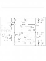
I'm seriously interested on these version (JLH2003) If someone knows a PC boards layout that would be a great help.
I know on Ebay readily available and cheap but that does not feet my heatsink. 🙂 If it would be at least 5" longer These amp run hot and I do have a set over sized heatsink, the best would be if I could find a longer version layout a la N Pass F series (original) for the best heat transfer. If there is a thread for these version I apologies I posted here, I did not found much about these JLH 2003 version.
Thanks for any help.
Greets.
Attachments
Hi gaborbela
There a few versions of Geoff Moss' JLH 2003 update amplifier that simply have a second pair of output transistors and emitter resistors added in parallel, as your diagram shows: The Class-A Amplifier Site - JLH Class-A Update
There is probably no reason these can't be fitted to the heatsink with flying leads, just as the original JLH prototypes were. Siliconray's JLH69 clone kit also uses that simple technique, see posts #6-8 here: http://www.diyaudio.com/forums/sili...200659-free-pcb-jlh-2005-class-amplifier.html
Last edited:
Hi gaborbela
There a few versions of Geoff Moss' JLH 2003 update amplifier that simply have a second pair of output transistors and emitter resistors added in parallel, as your diagram shows: The Class-A Amplifier Site - JLH Class-A Update
There is probably no reason these can't be fitted to the heatsink with flying leads, just as the original JLH prototypes were. Siliconray's JLH69 clone kit also uses that simple technique, see posts #6-8 here: http://www.diyaudio.com/forums/sili...200659-free-pcb-jlh-2005-class-amplifier.html
Thank you for your answer
I do not like to use flying leads especially at high biased Class A amplifier, out of bad experience.
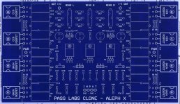
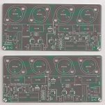
Ones I modified my AX for better heat spread and it messed up the sound of the amp so badly, sounded thin like total different amp. Thank God I only modified one side at the time. May be the wire I used made the difference. It was a 16AWG Teflon silver plated wire about 3" per side. I will attach the PC board for better understanding. AX run 7A total bias per channel.
I do like these JLH 2003 boards from Ebay I wish they would be 4-5 inch longer to feet my heatsink. If I do not found better I will buy those and will give a try. https://www.youtube.com/watch?v=oaR20OYACM8&t=2s I think the guy has some heat issue he uses several fans. The another built version, I do like what I hear!🙂https://www.youtube.com/watch?v=W7ocFZFh2MM
Greets
Attachments
I have never managed to make the pcb siliconray work well.Hi gaborbela
There a few versions of Geoff Moss' JLH 2003 update amplifier that simply have a second pair of output transistors and emitter resistors added in parallel, as your diagram shows: The Class-A Amplifier Site - JLH Class-A Update
There is probably no reason these can't be fitted to the heatsink with flying leads, just as the original JLH prototypes were. Siliconray's JLH69 clone kit also uses that simple technique, see posts #6-8 here: http://www.diyaudio.com/forums/sili...200659-free-pcb-jlh-2005-class-amplifier.html
I tried different configuration without success.
From my point of view, the original jlh surpasses them
There is probably no reason these can't be fitted to the heatsink with flying leads, just as the original JLH prototypes were.
The original JLH is "unconditionally stable". Most of what people build is not original so the JLH prototype example is irrelevant.
Thank you for your answer
I do not like to use flying leads especially at high biased Class A amplifier, out of bad experience.
Ones I modified my AX for better heat spread and it messed up the sound of the amp so badly, sounded thin like total different amp. Thank God I only modified one side at the time. May be the wire I used made the difference. It was a 16AWG Teflon silver plated wire about 3" per side. I will attach the PC board for better understanding. AX run 7A total bias per channel.
I do like these JLH 2003 boards from Ebay I wish they would be 4-5 inch longer to feet my heatsink. If I do not found better I will buy those and will give a try. https://www.youtube.com/watch?v=oaR20OYACM8&t=2s I think the guy has some heat issue he uses several fans. The another built version, I do like what I hear!🙂https://www.youtube.com/watch?v=W7ocFZFh2MM
Greets
Thats my amplifier 😎
https://www.youtube.com/watch?v=W7ocFZFh2MM
HI
I'm seriously interested on these version (JLH2003) If someone knows a PC boards layout that would be a great help.
I know on Ebay readily available and cheap but that does not feet my heatsink. 🙂 If it would be at least 5" longer These amp run hot and I do have a set over sized heatsink, the best would be if I could find a longer version layout a la N Pass F series (original) for the best heat transfer. If there is a thread for these version I apologies I posted here, I did not found much about these JLH 2003 version.
Thanks for any help.
Greets.
oddwires.com also sells one here,
JLH Class A Amplifier Board - oddWires
That is the low power version, the PC board layout even worst to match my heatsinks. I want to use min 2 pair power devices.
Thanks anyway! 🙂
I will post some picture from the heatsink I plan to use so it will be easier to understand my problem...
On the end I will try flying leads if I do not found any better solution.
Great sound! Nice amp it match that speaker well. My taste🙂
By any chance do you have some picture from inside the amp....😀
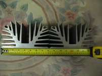
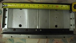
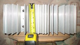
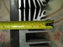
Some pictures from the mentioned heatsinks, I will use two of these for a stereo...
It would be the best if the power devices will be mounted at the center of each heatsink for better heat transfer.
Also the it has much more thickness at that place of each heatsink.
It would be the best if the power devices will be mounted at the center of each heatsink for better heat transfer.
Also the it has much more thickness at that place of each heatsink.
Attachments
- Home
- Amplifiers
- Solid State
- JLH 10 Watt class A amplifier