On your second case, the slow turn on of the LEDs only occurs when the Calvin board is fitted and if I remember correctly I had to tweak the pot on the Calvin board to get the side LEDs on at all - however this maybe a red herring and I need to double check this by turning the pot to each end stop and powering up the board. I'm just wary of popping some component on the boards.
The boards, when running sound fabulous...
Sent from my SM-G930F using Tapatalk
Still, it would be interesting to get measurements, in the form of some graphs, showing the 'boot'-phase voltages and currents. Any one? 🙂
My own set is run with 8.2 ohm resistors in the shunt and it takes about 20 seconds for all the leds to come on, they come on pretty evenly, within half a second of each other at just over 11v on the output.
I could do a series of start up videos, then overlay the voltages around the circuit in a top down sort of display, so you can see them in real time. I don't have any other way to do data capture like that.
I could do a series of start up videos, then overlay the voltages around the circuit in a top down sort of display, so you can see them in real time. I don't have any other way to do data capture like that.
Could you capture this data using a DSO? (set for a slow time base 2sec/div and manual trigger at the same time as switching on the Paradise, this will create the graphs needed).
In the meantime, here's what has been keeping me busy for the past few nights.
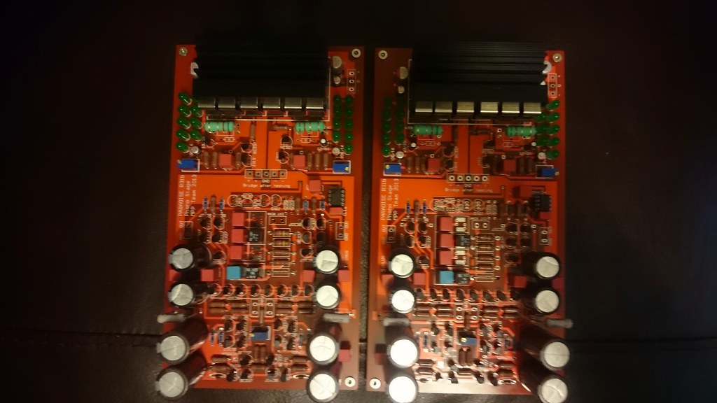
All stuffed, time for testing and checking the Calvins.
All stuffed, time for testing and checking the Calvins.
So turns out I have an error on the negative rail on one board. 18v at join to back end, 18v at first test point, correct voltages feeding riaa section, but only 8.4v after the 120r. All solder good, no misplaced parts.
Have tested with another psu board with same result, so fault is between input and 120r. Time to start pulling parts...
Bugger.
Doubly so because pair is for joachim...
Have tested with another psu board with same result, so fault is between input and 120r. Time to start pulling parts...
Bugger.
Doubly so because pair is for joachim...
So turns out I have an error on the negative rail on one board. 18v at join to back end, 18v at first test point, correct voltages feeding riaa section, but only 8.4v after the 120r. All solder good, no misplaced parts.
Have tested with another psu board with same result, so fault is between input and 120r. Time to start pulling parts...
Bugger.
Doubly so because this pair is for joachim...
I guess I could dig the manual out and see how it's done on my Rigol
And now, back to that manual ... hop..hop.. 🙂
From one PSU to another.And the first thing you do is power ON via a Mains Bulb Tester and measure the input and output voltages without any load connected.
From there you can calculate/predict the lowest and highest no load voltages from this new transformer.
Ok I got the transformers now,and at input I measured 239v and output 27,6v.
If that's ac out of the transformers then you'll need about 25r after the chokes in the psu to hit the target dc voltage on the main boards. If it's dc on the main boards I'd look to drop it to 25.5v, no benefit in sound going any higher.
Sq : but historia mains voltage is 239v when it is rated 230v, so you have to consider it can actually drop to 220 when it is low, and you should still have enough voltage into the paradise boards those times.
that allows you to predict the open circuit 230Vac secondary: ~26.5VacFrom one PSU to another.
Ok I got the transformers now,and at input I measured 239v and output 27,6v.
Divide by rated secondary (25Vac ?) to find the transformer regulation
26.5/25 = 1.062, gives regualtion = 6.2%
Measure the primary and secondary resistances and you have enough to let PSUD2 do all the calculations.
Role2k, you'll know your mains voltage, in Sheffield I never see even a 2v variance so I set and forget at 26.5v.
Has anyone dabbled with local regulation on their paradise? I'm wondering if splitting out the input stage onto its own local regs might not benefit the sound. Or go the whole hog and dump the shunt for six local regs.
Any thoughts or experiences?
Has anyone dabbled with local regulation on their paradise? I'm wondering if splitting out the input stage onto its own local regs might not benefit the sound. Or go the whole hog and dump the shunt for six local regs.
Any thoughts or experiences?
I`m down to 3 ohm on the resistor to get 25,8v DC out if the CCS is 130mA.
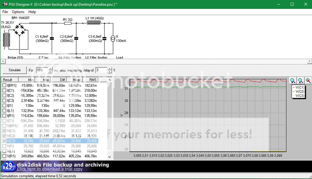
The Primary resistance is 166 ohm and the secondary is 9,4 ohm.
The Primary resistance is 166 ohm and the secondary is 9,4 ohm.
- Home
- Source & Line
- Analogue Source
- Paradise Builders